
- YS TECH USA Inc blog
- Thermal Management,
- Edge Computing,
- Quality Standards,
- GPU Cooling,
- AI Hardware
- Thermal Management for Military AI Hardware: Designing Cooling Systems That Meet MIL-STD-810
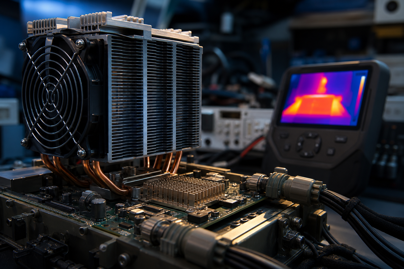
Thermal management for military AI hardware is a compliance issue before it is a cooling issue. If edge compute, GPU modules, and power stages cannot survive the temperature, shock, vibration, humidity, dust, and altitude profiles defined in MIL-STD-810, the system may pass a lab bench check and still fail in the field. That failure shows up as throttling, boot instability, shortened component life, and schedule loss when the first prototype has to be reworked.
MIL-STD-810 is not a certification badge. It is a test framework that forces the design team to prove the hardware can survive the real environment it will see in service, and that changes the way fans, blowers, heatsinks, connectors, and enclosure airflow must be selected. The cooling path has to be part of the ruggedization plan from the first layout review, not a late fix after junction temperatures run hot.
For teams building military AI hardware, that distinction matters. The right thermal cooling solutions do more than move air. They preserve margin, protect reliability, and keep the platform inside its operating envelope when the enclosure is sealed, the vehicle is vibrating, the air is thin, or the ambient temperature climbs past what a commercial design can tolerate.
Table of Contents
- Why Military AI Hardware Fails Without Thermal Design Discipline
- What MIL-STD-810 Means for Cooling-System Design
- Choosing Fans, Blowers, and Heatsinks for Rugged AI Enclosures
- Designing for Dust, Shock, Altitude, and Temperature Extremes
- Using CFD, Validation Testing, and Iteration to Reduce Re-Spins
- How YS Tech USA Supports Military-Grade Thermal Solutions
- Key Takeaways
- FAQ
- About YS Tech USA
- Request a Thermal Design Review
Why Military AI Hardware Fails Without Thermal Design Discipline
Military AI hardware fails fast when thermal design is treated as a final accessory. Edge AI processors, GPUs, and high-speed power electronics raise junction temperature quickly, and the thermal resistance stack from die to ambient gets ugly inside dense enclosures with limited airflow.
A commercial airflow concept can look fine in free air and still miss the target once cable harnesses, filters, board shields, and sealed panels go in place. The field failure is rarely mysterious. It usually starts with poor heatsink selection, weak airflow paths, or an ambient assumption that was 15 to 20 degrees too optimistic.
The schedule risk is just as real as the reliability risk. A cooling issue found after hardware freeze usually means a board re-spin, a mechanical revision, or a fan change that ripples into connectors, labels, mounting, and qualification work.
Defense programs also live with harsher thermal realities than most commercial systems. Modus Advanced notes that defense thermal systems may need to operate from -65°C to over 1100°C (-85°F to 2000°F+) in some environments, and that commercial parts can fail within minutes under those conditions, which is why defense thermal management and military standards must be treated as a system requirement rather than a component choice.
The Heat Density Problem Starts at the Silicon
AI accelerators pack more compute into less space, which raises thermal density around the junction and leaves less room for error. That is where heatsink geometry, airflow impedance, and fan static pressure curves start to matter more than catalog airflow numbers.
DARPA's Thermal Management Technologies program says rising DoD power consumption and shrinking system size make heat density a primary obstacle to further system growth. The program also states that its near-junction thermal transport effort targets a 3x or greater improvement in power handling from GaN power amplifiers, which shows how directly thermal performance limits system capability.
According to TMT, Increasing power consumption combined with decreasing system size in DoD systems leads to higher heat density, which is a major challenge for thermal management. Source
Late Thermal Fixes Cost More Than Parts
When cooling is added late, the team pays in time, not only in watts. A mounting pattern change can trigger mechanical validation, and a fan change can affect acoustic noise, current draw, connector selection, and test documentation.
I have seen a clean thermal model turn into a bad prototype because the enclosure was assumed to breathe when it was actually nearly sealed. That is a specification problem, not a manufacturing surprise.
What MIL-STD-810 Means for Cooling-System Design
MIL-STD-810 sets the environmental proving ground, then leaves the design team to build hardware that survives it. The standard is not a single certification, and Blue Line's overview of MIL-STD-810 notes that it is a U.S. Department of Defense environmental testing framework with nearly 30 laboratory methods covering real-world stresses.
For thermal design, the relevant stresses are temperature extremes, thermal shock, vibration, mechanical shock, humidity, dust and sand, and altitude. Jama Software notes that MIL-STD-810 was first published in 1962 and has been updated regularly since then, while Cybernet's reliability summary for military-grade electronics points to no less than 29 test methods, which shows how broad the framework is in practice.
The operational implication is simple. The cooling architecture has to survive the test profile, not just cool the board on a quiet day in the lab. Ruggedization changes fan selection, connector choice, sealing strategy, bearing type, and the way airflow moves through the enclosure.
The Standard Tests the Environment, Not Your Marketing Claim
MIL-STD-810 validates whether the hardware can keep working under the conditions it will face in service. That means the team has to tailor the test plan to the deployment, since a vehicle-mounted edge AI node, an airborne processor, and a sheltered rack unit do not see the same stress mix.
Blue Line also notes that tailoring is part of the framework, which matters because the test selection drives the thermal architecture. If the platform sees dust loading, altitude, and vibration together, the cooling design must account for reduced heat rejection, greater airflow impedance, and shorter fan life.
Cooling Design Follows the Enclosure Environment
A sealed enclosure, a vented enclosure, and a filtered enclosure each create different thermal risks. The wrong choice can push the design into a corner where there is no margin left for temperature rise, pressure drop, or connector movement.
That is why rugged electronics do not start with a fan part number. They start with the environmental envelope, then move to thermal resistance targets, airflow path design, and the validation plan that proves the result.
Choosing Fans, Blowers, and Heatsinks for Rugged AI Enclosures
The right answer depends on enclosure geometry, heat load, and allowable pressure drop. In tight military AI hardware, axial fans, centrifugal blowers, and heatsinks each solve a different part of the problem, and the best design usually uses more than one.
Axial fans move air well in low-impedance paths. Centrifugal blowers perform better when the airflow path includes bends, fins, filters, or compact ducting. Heatsinks carry the burden of spreading heat away from the source, but their value falls quickly if the airflow does not match the fin density and pressure loss.
A reliable selection also depends on bearing type, PWM control, IP rating, connector style, and the thermal resistance of the heatsink geometry. When a design needs high static pressure, the free-air CFM number stops being the main decision point.
Free-air Airflow Is Not the Number That Matters Most
High static pressure matters when airflow has to push through filters, narrow channels, and dense fin stacks. That is common in rugged electronics where the enclosure is built to keep out dust, moisture, and handling damage.
The same rule applies to heatsinks. A low-resistance sink can look attractive on paper, but if the airflow path is poor, the temperature rise at the device can still exceed the target by a wide margin.
Bearing Choice and Sealing Decide Life in the Field
Bearing selection changes life expectancy, noise, and resistance to heat and shock. PWM control helps the system respond to load changes without overcooling at light duty, while sealed connectors reduce the chance of failure during vibration and maintenance.
YS Tech USA lists IP43, IP55, IP56, and IP68 designs for difficult environments, along with sealed connectors, PWM integration, and multiple bearing options. That mix matters because military AI hardware often needs the cooling solution to work as part of a sealed system, not as a loose collection of parts.
Designing for Dust, Shock, Altitude, and Temperature Extremes
Environmental reality changes the cooling strategy as much as the power budget does. Dust, shock, altitude, and temperature extremes reduce margin in different ways, so the enclosure strategy must be chosen with the mission profile in mind.
A sealed enclosure protects against ingress, but it increases heat rejection difficulty. A ventilated enclosure rejects heat more easily, but it raises exposure to dust, humidity, and contamination. The design team has to choose the failure mode it can tolerate, then validate that choice with testing.
MIL-STD-810 testing makes those tradeoffs visible. If the platform sees shock and vibration, the fan mount, heatsink attachment, and connector retention need to survive repeated stress without loosening or cracking.
Dust and Sealing Create a Direct Thermal Tradeoff
The more tightly the enclosure is sealed, the harder it is to move heat out. That is where pressure-capable fans, duct design, and heatsink selection become central to the thermal budget.
If the design uses ingress protection to survive sand or dust, the airflow path must be planned early. Otherwise the system may meet the sealing target and miss the temperature target, which is a common way to fail late in qualification.
Altitude Cuts Cooling Margin Faster Than Many Teams Expect
Reduced air density lowers convective heat transfer and reduces fan effectiveness. At altitude, a design that looked safe at sea level can lose enough margin to push the junction temperature into a poor operating zone.
That is why derating matters. If the system is expected to operate in thin air, the cooling solution needs to be selected and validated for that condition, not for the easiest point in the envelope.
Shock and Vibration Punish Weak Mechanical Choices
A cooling system can fail mechanically before it fails thermally. Loose fasteners, poor connector retention, and weak fan mounts often become the real problem once the platform is exposed to vibration and handling shock.
7Starlake's published rugged compute data shows how serious these levels can be in practice, with products documented at 1.1 Grms and 10 g, 2.2 Grms and 20 g, and even 5.0 Grms and 40 g for vibration and shock testing. Those numbers are a reminder that the cooling structure has to be part of the ruggedization plan, not a separate afterthought.
According to Defense, Rugged compute products have been tested to vibration levels up to 5.0 Grms and shock levels up to 40 g, demonstrating the severity of mechanical stresses in military environments. Source
Using CFD, Validation Testing, and Iteration to Reduce Re-Spins
CFD and thermal simulation are the difference between a guessed cooling path and a defendable one. They show where air stalls, where dead zones form, and which components see the highest local temperature before the first prototype is built.
That matters because the cost of a bad guess is high. A late airflow correction often forces a new fan, a new heatsink, a new mounting bracket, or a new enclosure opening, and each change adds time to the NPI schedule.
Thermal collaboration early in the program shortens the path to a qualified design. It also gives mechanical, thermal, and NPI teams a shared basis for decision-making when tradeoffs appear.
Simulation Should Lead the Prototype, Not Follow It
CFD analysis helps teams predict airflow direction, pressure loss, and hotspots around processors, voltage regulation stages, and memory modules. Thermal simulation then tests the effect of ambient rise, altitude, and enclosure sealing before any hardware is cut.
YS Tech USA supports design analysis and thermal modeling, which helps reduce the guesswork that usually drives re-spins. When the thermal path is modeled before tooling, the first prototype has a much better chance of surviving test.
Validation Turns Theory into Evidence
Validation testing closes the gap between model and field reality. Reliability data, pressure curves, and mechanical test results give the program a defensible record for internal reviews and customer audits.
That record matters in military AI hardware, where the cooling choice has to survive both the environment and the review process. If the data package shows the fan, blower, and heatsink can meet the load, the team is in a much stronger position at design freeze.
How YS Tech USA Supports Military-Grade Thermal Solutions
YS Tech USA gives engineering teams a way to build the cooling system as a single thermal architecture instead of separate parts. The company combines fans, blowers, EC motors, and heatsinks so thermal engineers and NPI teams can match airflow, pressure, acoustics, and packaging in one design cycle.
That matters when the platform has to survive harsh-use conditions and still meet schedule. US-based engineering support, global production, and customization for sealed or high-pressure applications give OEM and contract manufacturing teams a practical path from concept to release.
The company's strength is not just product breadth. It is the ability to modify base models, adjust connectors, support PWM integration, and produce value-added assemblies that fit the mechanical constraints of rugged electronics.
Built for Defense-style Environmental Stress
YS Tech USA's rugged design approach fits the needs of military AI hardware that sees vibration, heat, moisture, and airflow restrictions in the same package. For teams working through MIL-STD-810 requirements, that combination reduces the chance that the cooling system becomes the weak link.
The result is a more stable thermal margin and a cleaner path through validation. A better first pass saves tooling, time, and schedule.
Why the Engineering Partnership Matters
The strongest thermal outcomes come from early collaboration, not last-minute part replacement. When the airflow path, heatsink choice, and sealing approach are solved together, the program gets a cooling system that fits the real enclosure rather than the ideal one.
We work with teams that need thermal cooling solutions built for high reliability thermal design, not catalog shortcuts. That is the difference between passing a review and passing the field.
Key Takeaways
- Thermal management for military AI hardware has to be set at the specification stage, because late cooling fixes raise risk, delay qualification, and often force re-spins.
- MIL-STD-810 is a testing framework, not a certification, and it pushes the design team to prove performance under temperature, shock, vibration, humidity, dust, and altitude stress.
- Fans, blowers, and heatsinks must be selected together, with static pressure, bearing choice, PWM control, sealing, and enclosure airflow treated as one system.
- CFD, thermal simulation, and validation testing reduce guesswork and give NPI teams evidence before the first prototype becomes expensive.
- Rugged cooling succeeds when the mechanical, thermal, and compliance requirements are solved in the same design cycle.
FAQ
Q: What makes MIL-STD-810 important for military AI hardware?
A: MIL-STD-810 matters because it checks whether the hardware can keep working in the environmental conditions it will actually see. For military AI hardware, that includes hot and cold extremes, vibration, shock, humidity, dust, and altitude. The standard does not pick the cooling solution for you, but it forces the team to prove the design survives the mission profile. That is why thermal management has to be part of the compliance plan from the start.
Q: Why do axial fans often fail in rugged enclosures?
A: Axial fans can fail when the enclosure has too much airflow impedance. Filters, short ducts, dense heatsinks, and tight packaging raise static pressure demand beyond what a free-air fan can deliver. In that case, the system may move air in the lab and still run hot in the field. A blower or a higher-pressure fan may be the right fit when the enclosure is sealed or tightly constrained.
Q: How does altitude change cooling performance?
A: Altitude lowers air density, which reduces heat transfer and fan effectiveness. A design that passes at sea level may lose enough margin at altitude to push components into thermal throttling or a reduced life curve. That is why derating and validation at the intended operating altitude matter. Cooling systems for military AI hardware should be checked against the full environment, not only the easiest test condition.
Q: What evidence should an NPI buyer ask for before release?
A: Ask for CFD output, thermal simulation results, fan and blower performance curves, and validation data tied to the intended environmental profile. You also want connector, sealing, and mounting details that match the shock and vibration plan. If the supplier can show how the cooling path was tested against the enclosure, the program has a much better chance of holding its schedule. That evidence matters as much as the part number.
Q: How do heatsinks fit into a rugged cooling strategy?
A: Heatsinks are the heat spreaders that move energy away from the device before airflow removes it. Their geometry has to match the airflow path, or the thermal resistance stays too high. In rugged electronics, heatsinks also have to survive shock, vibration, and long service life without loosening or distorting. The right sink is the one that works inside the enclosure, not just on a bench.
Q: Can a custom thermal design reduce re-spins?
A: Yes. A custom approach lets the team match the fan, blower, heatsink, and connector strategy to the actual load and enclosure constraints. That cuts the chance of finding a thermal miss after the prototype is built. It also reduces the need to change the mechanical design late in the program. For military AI hardware, that saves time and protects the qualification schedule.
About YS Tech USA
YS Tech USA is a premier designer and manufacturer of thermal solutions, specializing in low noise, high-performance DC axial fans, blowers, and heat sink technologies. Located in Huntington Beach, California, we deliver reliable, high-quality products for demanding applications across various industries.
At YS Tech USA, we offer the best of both worlds: the capabilities of a large company with the personalized service of a small one. We collaborate closely with our customers to understand their specific thermal needs and provide customized solutions tailored to their unique requirements.
Our extensive product range includes both modified standard and custom solutions, designed to tackle a wide array of thermal challenges. Whether you need a high-performance fan for a new project or a custom heat sink for an existing application, our team is ready to assist.
With over three decades of industry experience, YS Tech USA has a proven track record of delivering innovative and effective thermal solutions. Contact us today to discover how we can help you address your thermal control challenges.
Request a Thermal Design Review
If your military AI hardware has not had a full airflow and heatsink review yet, the safest time to do it is before the first prototype locks in the wrong thermal architecture. Request a thermal design review for your military AI hardware, and let us help you evaluate airflow, heatsink strategy, and rugged cooling architectures before a costly re-spin starts.
Read On

Mistakes to avoid when selecting thermal management fans for automotive electronics reliability
Heat kills electronics.

Thermal cooling methods for microwave communication equipment: insights from a telecom industry expert
Meet Dr. Lena Rivera, a seasoned telecommunications engineer specializing in thermal management...

Thermal Management for AI Hardware on the Factory Floor
A PLC that once ran comfortably at 5 to 15 watts can give way to a Jetson Orin drawing 40 to 60...