Thermal management looks complicated when a product is already hot and the schedule is slipping. It becomes much simpler when you treat heat as a design input from day one.
That approach protects reliability, cuts rework, and keeps the final product closer to the performance target you set in the first place.
A recent PCB thermal design guide from ALLPCB says poor thermal management can cause component failure, reduced lifespan, and compromised performance. Number Analytics says thermal management begins at the design stage, which matches what I have seen on real programs.
The pattern is consistent across automotive, medical, industrial, telecom, and power electronics. The teams that solve heat early ship cleaner builds and spend less time chasing temperature problems after validation.
Key Takeaways
- Put the heat path in the design before the first prototype, not after the first failure.
- Use thermal vias, copper, and placement before you add larger hardware.
- Match the thermal interface material to the load and the assembly method.
- Choose air, hybrid, or liquid cooling based on actual heat density, not habit.
- Validate with CFD and thermal analysis before tooling locks in the wrong answer.
Table of Contents
- Why thermal decisions need to happen early
- How to build a better heat path
- How to choose the right thermal interface material
- How component placement protects reliability
- How to match cooling architecture to heat density
- Final checks before release
Why Thermal Decisions Need To Happen Early
The simplest reliability gain comes from making thermal choices before layout is frozen. Once the board, enclosure, and airflow path are locked, every fix costs more and usually gives less.
YS Tech USA has said it plainly in its own thermal-design work: thermal decisions made late in development cost weeks of rework, surprise warranty expenses, and customer frustration. That is especially true in programs that must hit 85°C, 90°C, or 105°C operating classes in automotive and industrial use.
A good starting point is a quick thermal review during concept and schematic stages. That review should answer three questions: where the heat starts, where it goes, and what the product can tolerate without losing reliability.
How To Build A Better Heat Path
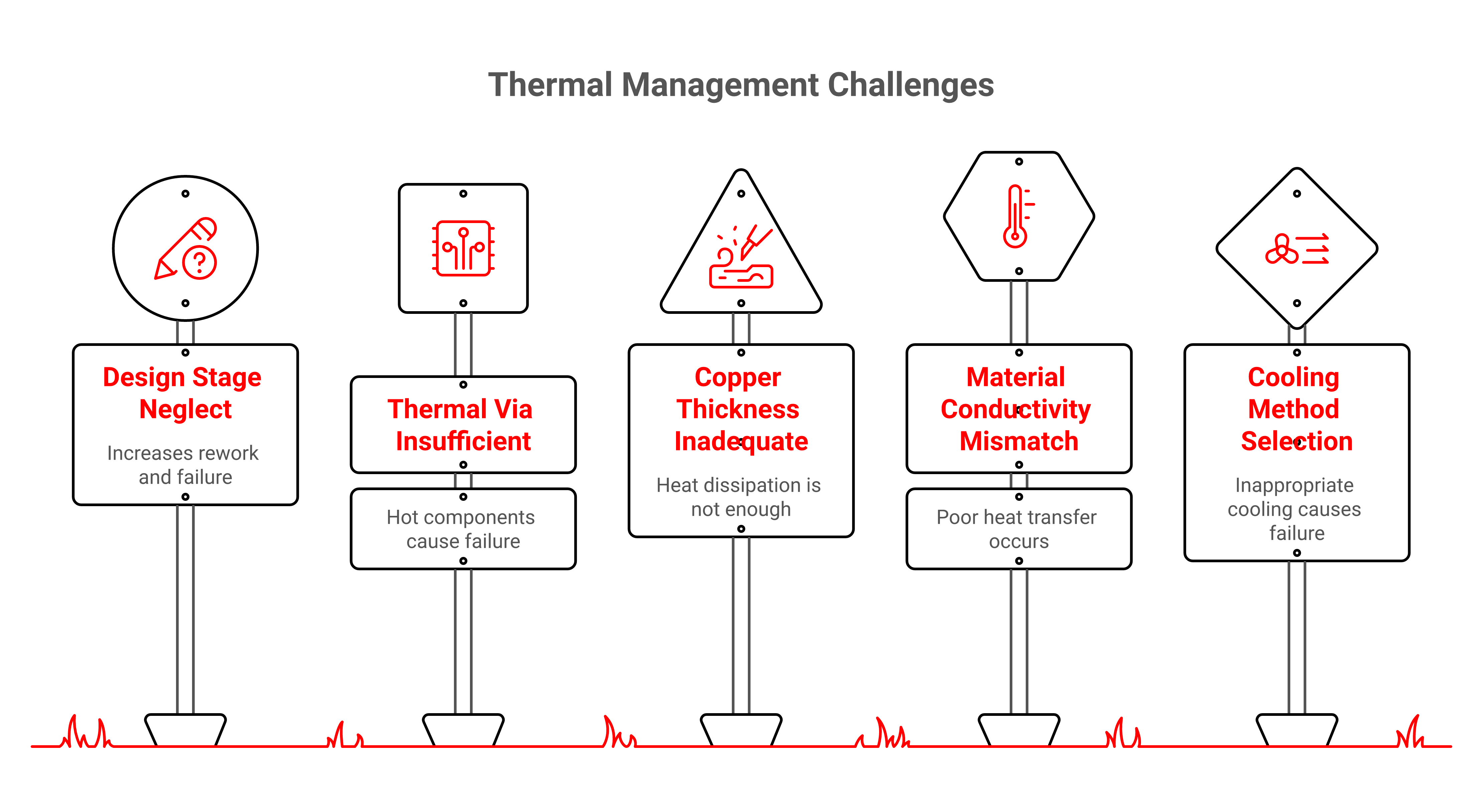
A better heat path usually begins with simple board-level changes. Power Systems Design recommends increasing copper thickness and adding thermal vias directly beneath hot components so heat can move into a spreader or cooler surface.
I have seen this save programs that were close to failure on paper. A few well-placed vias and a better copper path often remove enough thermal resistance to delay or eliminate a bigger fan or heat sink.
The practical lesson is direct. Before you enlarge the cooler, ask whether the board is trapping heat in the first place.
How To Choose The Right Thermal Interface Material
The thermal interface material is often the easiest place to lose performance. A poor interface can cancel out a strong heat sink, while a good one can make a modest cooling stack behave well.
Number Analytics gives useful numbers here. It reports thermal grease at about 0.5 to 5 W/mK and 0.1 to 1 °C/W, thermal pads at 1 to 10 W/mK and 0.1 to 10 °C/W, phase change materials at 1 to 10 W/mK and 0.01 to 0.1 °C/W, and solder-based TIMs at 50 to 100 W/mK and 0.01 to 0.1 °C/W. Those ranges matter because they show how much the interface can change the final junction temperature.
The right choice depends on assembly repeatability, pressure, serviceability, and cost. In a high-reliability build, the best TIM is the one that stays consistent after thermal cycling, vibration, and production variation.
How Component Placement Protects Reliability
Placement is one of the cheapest thermal decisions you will ever make. If power devices, processors, or high-loss components sit in dead air or near each other, the rest of the system has to work harder to recover.
Number Analytics says power electronics and high-speed processors should be placed in areas that allow for efficient heat dissipation. That is simple advice, but it changes outcomes because it reduces localized hot spots before the enclosure ever sees a fan curve.
I would rather move a part on a layout than add a larger cooler after test failure. Moving the part is cleaner, cheaper, and usually better for long-term reliability.
How To Match Cooling Architecture To Heat Density
The cooling method should fit the heat load, not the lowest-cost catalog option. Power Systems Design recommends moving from package improvements to copper and vias, then to heat sinks or heat pipes, and finally to forced-air cooling when passive methods cannot hold junction temperature.
That sequence still works in many products. But density is rising fast in servers, EV charging, power conversion, and compact industrial systems. Diabatix reports average rack densities in the 10 to 20 kW range, while AI and accelerated compute racks are moving to 50 to 100 kW and beyond. The same source cites analysis showing air cooling remains effective up to around 20 kW per rack, but performance and PUE begin to fall sharply as density reaches 40 to 80 kW.
That is why liquid and hybrid cooling keep gaining ground. Persistence Market Research projects the U.S. Thermal management technologies market at US$5.8 billion in 2026, growing to US$9.8 billion by 2033 at a 9.4% CAGR, with Data Centers & Servers at 30% market share and Advanced & Liquid Cooling Devices at 28%.
Final Checks Before Release
The last step is not to add more hardware. It is to verify that the thermal plan still holds under real conditions, including airflow impedance, tolerance stack-up, and production variation.
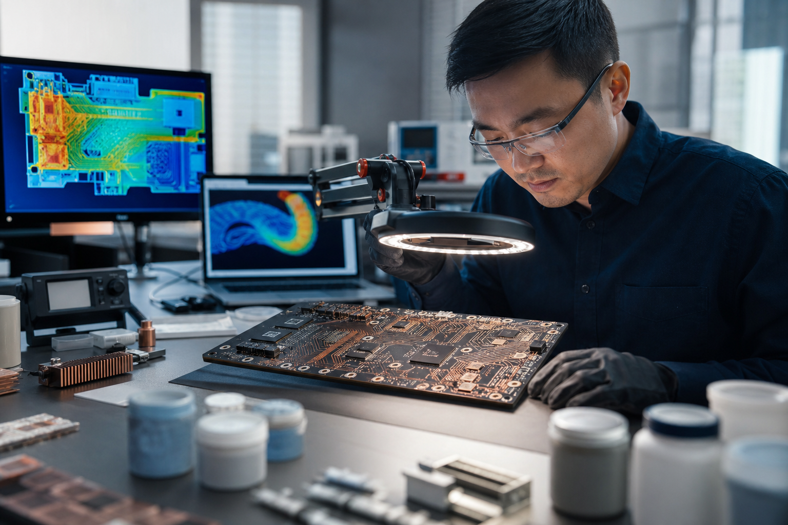
YS Tech USA uses CFD, FEA, and thermal simulation because those tools catch mistakes before they become re-spins. That is especially useful when a product must meet quiet operation, water resistance, PWM control, and high-temperature targets in the same design.
If you want a reliable product, keep the thermal plan simple and verify it early. That approach protects schedule, margin, and field life.
Thermal Choices That Hold Up In The Field
Four simple moves get you most of the way there, and they all point in the same direction. Start the heat path early, use the right interface, place the hot parts with intent, and pick the cooling architecture that matches the actual load.
Do that, and reliability stops being a late-stage rescue effort. It becomes part of the design from the start.
| Angle explored | What it reveals | Plain implication for thermal engineer, Mechanical engineer |
|---|---|---|
| Early thermal design | Heat becomes a reliability issue before the first prototype | Review thermal limits during concept and schematic stages |
| Heat path planning | Copper and vias reduce resistance before bigger hardware is needed | Improve the board first, then size the cooler |
| Thermal interface choice | TIM performance changes junction temperature more than many teams expect | Match the material to assembly repeatability and service needs |
| Component placement | Hot parts add avoidable heat when they are clustered or boxed in | Move heat sources to places with a clear dissipation path |
| Cooling architecture | Air works up to a point, then density pushes the design toward liquid or hybrid cooling | Choose the cooling method from the real heat load, not the default catalog option |
FAQ
Q: What is the simplest way to improve thermal reliability?
A: Start with layout and heat path, not with a bigger fan. Good placement, copper, and thermal vias often remove the biggest hotspots before hardware changes are needed. That keeps the design simpler and reduces the chance of fixing one problem while creating another. It also gives you a cleaner baseline for testing.
Q: When should I choose a different thermal interface material?
A: Change the TIM when the current material creates too much resistance, too much variation, or too much assembly risk. The numbers matter here, because thermal grease, pads, phase change materials, and solder-based TIMs behave very differently. A material that looks fine on a spec sheet can still fail in production if clamp force, cycling, or tolerance stack-up are ignored. Pick the TIM for the real build, not the ideal sample.
Q: How do I know if air cooling is still enough?
A: Start with the real heat load and the available airflow path. If the product sits in a density range where the air side keeps losing margin, then heat sinks, heat pipes, or forced air may no longer be enough. In dense racks, the shift toward liquid or hybrid cooling is already happening for a reason. It is a reliability decision as much as a performance one.
Q: Why does component placement matter so much?
A: Placement changes how easily heat leaves the board. If hot parts sit too close together or in dead zones, the cooler has to work harder and the whole system runs hotter. Better placement lowers local temperature rise before you spend money on larger thermal hardware. That often improves both reliability and acoustic performance.
Q: What role does simulation play in thermal design?
A: Simulation shows where the heat will go before you build expensive hardware. CFD and thermal analysis help you spot dead zones, pressure drop issues, and bad component placement early. That is why a simulation-led approach cuts re-spins and shortens development time. It gives the team a chance to correct the design while changes are still cheap.
Q: How does this approach fit NPI programs?
A: It fits well because it keeps the design practical from the start. NPI teams need parts that work in production, not just in a lab sample. A simple thermal plan with the right fan, blower, or heat sink gives mechanical and thermal teams a cleaner path to validation. It also makes it easier to protect schedule when the first build arrives.
About YS Tech USA
YS Tech USA is a premier designer and manufacturer of thermal solutions, specializing in low noise, high-performance DC axial fans, blowers, and heat sink technologies. Located in Huntington Beach, California, we deliver reliable, high-quality products for demanding applications across various industries.
At YS Tech USA, we offer the best of both worlds: the capabilities of a large company with the personalized service of a small one. We collaborate closely with our customers to understand their specific thermal needs and provide customized solutions tailored to their unique requirements.
Our extensive product range includes both modified standard and custom solutions, designed to tackle a wide array of thermal challenges. Whether you need a high-performance fan for a new project or a custom heat sink for an existing application, our team is ready to assist.
With over three decades of industry experience, YS Tech USA has a proven track record of delivering innovative and effective thermal solutions. Contact us today to discover how we can help you address your thermal control challenges.
Author
Charlie Taylor: Charlie is a seasoned industry executive with a demonstrated history of working in the electronics manufacturing industry supporting engineers and buyers with ideas and technical support for fans, blowers and heat sinks.
Read On