Key Takeaways
- Automotive thermal management is moving fast because the market is large and still growing. Coherent Market Insights estimates the global market at USD 109.02 billion in 2026, with a path to USD 166.11 billion by 2033, while Fortune Business Insights projects growth from USD 51.27 billion in 2026 to USD 85.24 billion by 2034.
- The fastest way to reduce re-spins is to define thermal requirements before hardware selection locks in. CFD, boundary condition checks, and early airflow validation reduce prototype churn and keep the design team from guessing late in the program.
- You need to specify airflow, pressure drop, ingress protection, control signals, noise limits, and validation criteria as one system. When those items are separated, the fan is usually blamed for a problem created by the enclosure, control logic, or mounting stack-up.
- Automotive programs around infotainment, LED headlights, seat ventilation, air purification, fragrance distribution, autonomous systems, and safety sensors all need different thermal architectures. A shared framework saves time, but each application still needs its own thermal target.
- A structured sprint plan gives mechanical engineers, thermal engineers, and NPI teams a repeatable path from requirements to release. That path is where design accuracy, time-to-market, and field reliability improve together.
Introduction
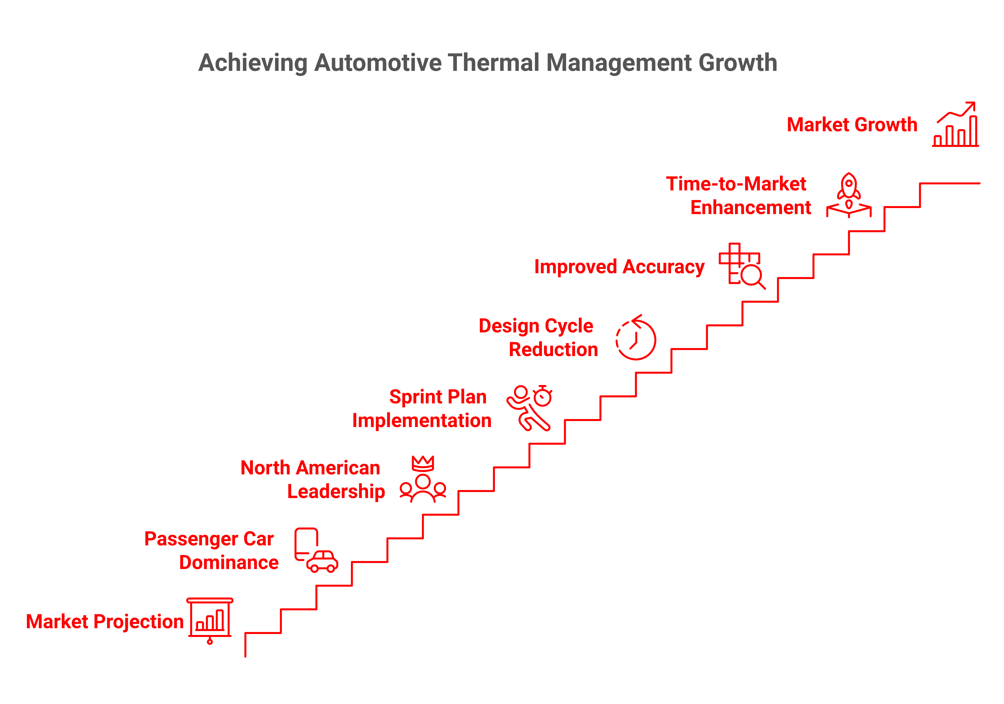
Automotive thermal management is now a design problem with market pressure behind it, not a late-stage sourcing exercise. Coherent Market Insights places the automotive thermal management market at USD 109.02 billion in 2026 and projects USD 166.11 billion by 2033 at a 6.2% CAGR. Passenger cars account for 60.2% of that 2026 share, and North America leads with 39.9%, which tells you where much of the engineering pressure sits.
The practical answer is simple. Start thermal work early, validate airflow with CFD, and tie the cooling architecture to the real electrical and mechanical limits of the program. In underhood and in-cabin designs, the cost of waiting is usually a re-spin, a hotter junction temperature, or a control issue that appears only after tooling is underway.
This sprint plan lays out eight steps that automotive engineers can follow in sequence. It uses application-specific checks, schedule discipline, and the kind of thermal decision-making that keeps a program from drifting into trial-and-error.
Table of Contents
- Key Takeaways
- Introduction
- 8-Step Sprint Plan
- Release Criteria for the Cooling Architecture
- FAQ
- About YS Tech USA
8-Step Sprint Plan
Automotive thermal work moves faster when the team treats it as a planned sequence instead of a series of reactive fixes. Follow this eight-step plan and a typical concept-to-release cycle can be organized into four weeks, instead of stretching through repeated prototype loops.
If the work is unplanned, the team usually spends more time reconciling enclosure changes, fan swaps, and validation surprises than solving the original heat problem. That is why the sprint structure below starts with requirements and ends with validation, with each week closing one set of decisions before the next begins.
| Sprint | Goal | Timeframe | Completion criteria |
|---|---|---|---|
| Requirement capture | Define heat load, environment, and compliance targets | Week 1 | Thermal limits and operating conditions are frozen |
| Thermal modeling | Build physics-based CFD model with validated inputs | Week 1 to Week 2 | Reviewed model exists with defensible boundary conditions |
| Cooling architecture selection | Convert model into specific fan, blower, or heatsink path | Week 2 | Cooling topology selected and package fits enclosure |
| Control and noise strategy | Define PWM behavior, acoustic limits, and electrical protection | Week 2 to Week 3 | Control curve, noise target, and protections defined in release package |
| Environmental hardening | Match design to vehicle environment and exposure conditions | Week 3 | Design matched to real installation environment |
| Validation planning | Define test conditions and signoff criteria | Week 3 | Validation matrix complete and test setup matches design assumptions |
| Prototype review and correction | Close loop between hardware build and thermal requirements | Week 4 | Prototype gaps explained with clear corrective actions |
| Release and production handoff | Turn validated design into release-ready thermal package | Week 4 | Cooling solution released with validated performance and repeatable production path |
Sprint 1: Lock the Thermal Requirements, Week 1
This sprint sets the thermal target before parts are chosen, which is the right order for any automotive platform with limited packaging room.
- Define heat sources, ambient range, and duty cycle: Map the worst-case wattage, airflow path, and underhood or cabin temperature range so the design starts from the real load, not a nominal one.
- Confirm control and interface needs: Decide whether the program needs PWM, CAN, LIN, specialty connectors, or overvoltage protection so the cooling device can talk to the vehicle architecture.
- Set the environmental bar: Capture moisture exposure, waterproofing needs, and operating temperature targets such as 85C, 90C, or 105C so the design is sized for the field condition, not the lab bench.
Completion criteria: Thermal limits, interface needs, and environmental targets are documented and approved before any mechanical layout work begins.
Sprint 2: Build the Thermal Model, Week 1 to Week 2
This sprint turns the requirement set into a physics-based model, which is where early mistakes are cheapest to catch.
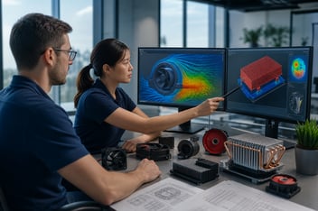
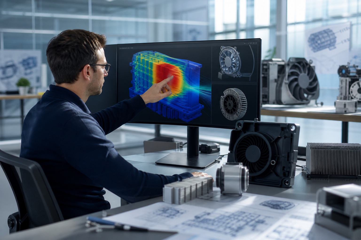
- Create the CFD model: Use underhood CFD guidance from Caliber Technologies to establish airflow paths, pressure losses, and hot spots before tooling.
- Test multiple concepts quickly: Same Sky notes that CFD can let engineers review dozens of design variations in hours or days instead of months of physical testing, which is a major advantage when packaging space is fixed.
- Challenge the inputs before trusting the result: CFD best practices from Same Sky call out the same issues automotive teams face, including boundary condition accuracy, input data uncertainty, and the need for enough expertise to read the output correctly.
Completion criteria: A reviewed model exists, the boundary conditions are defensible, and the team can explain why the result is credible.
Sprint 3: Select the Cooling Architecture, Week 2
This sprint converts the model into a specific fan, blower, or heatsink path, which is where product fit and acoustic limits start to matter.
- Match airflow to restriction: Choose axial fans, centrifugal blowers, or a heatsink-assisted package based on the actual pressure drop in the enclosure, not on free-air airflow alone.
- Tie the part to the use case: Infotainment, LED headlights, seat ventilation, air purification, fragrance distribution, autonomous sensors, and safety modules all need different pressure and noise behavior.
- Check form, fit, and function early: YS Tech USA can modify base commercial fan platforms to reduce tooling cost when a program needs a faster path to a qualified sample.
Completion criteria: The cooling topology is selected, and the package can fit the enclosure without forcing a late mechanical redesign.
Sprint 4: Engineer the Control and Noise Strategy, Week 2 to Week 3
This sprint is about how the cooling system behaves once it is installed, because field complaints often start with sound, cycling, or unstable control.
- Specify PWM behavior and ramp logic: Define how the fan responds under low load, peak load, and transient conditions so speed changes do not create noise spikes or thermal lag.
- Set acoustic limits: When a cabin-facing module is involved, low dBA is not a luxury item. It is part of the product requirement, especially for seat comfort, air purification, and infotainment.
- Include electrical protection from the start: Overvoltage protection and specialty connectors should be part of the first revision, not added after the first bench failure.
Vertiv reports that a unified thermal management system with intelligent control capability can improve efficiency by 10% to 20%. That figure matters because the same control discipline reduces wasted airflow and avoids running the cooling device harder than the load requires.
Completion criteria: The control curve, noise target, and electrical protections are defined in the release package.
Sprint 5: Match the Design to the Automotive Environment, Week 3
This sprint hardens the solution for the vehicle environment, which is where many otherwise good designs fail.
- Confirm ingress and moisture protection: Select the proper sealing approach for rain, spray, washdown, or condensation exposure, especially in lamps, exterior sensors, and underhood modules.
- Validate thermal range by location: A part that survives in the cabin may fail near the hood line, so the operating temperature must be tied to the installation point, not the vehicle label.
- Request automotive-specific options when needed: AECQ parts, CAN and LIN bus support, and mechanical poke-yoke upgrades can reduce assembly mistakes and support the launch plan.
ThermoAnalytics describes predictive, physics-based simulation across battery thermal management, cabin comfort, brake systems, exhaust systems, and heated or cooled seats. That range reflects the real issue in automotive programs, which is not a single heat source but several thermal zones that interact.
Completion criteria: The design is matched to the real installation environment and can survive expected exposure conditions.
Sprint 6: Build the Validation Plan, Week 3
This sprint defines how the team will prove the design before launch, which is where handoffs usually get weak if they are not written down.
- Set test conditions that mirror the model: Use the same airflow restrictions, ambient temperature, and mounting orientation that were used in CFD so the comparison is meaningful.
- Add hand-calculation checks: Electronics Cooling's thermal analysis best practices stress that analysis is not a button press, and the model should be checked against boundary conditions, thermophysical properties, and simple sanity checks.
- Keep one person accountable for the signoff path: If the team cannot explain why a measured result differs from the model, the program is not ready for release.
A Springer article on automotive HVAC performance and passenger comfort, published 17 June 2026, shows how much attention the industry is placing on algorithmic thermal control. That interest tracks with a simple reality, which is that comfort and component reliability now share the same thermal design space.
Completion criteria: The validation matrix is complete, and the test setup matches the assumptions used in design.
Sprint 7: Run Prototype Review and Correct the Gaps, Week 4
This sprint closes the loop between the first hardware build and the thermal requirements, which is where schedule risk becomes visible.
- Review measured junction temperatures: Compare the prototype against the target temperature margin and identify whether the gap comes from airflow, mounting, control logic, or enclosure loss.
- Check for assembly sensitivity: Small fit changes, connector placement, or seal compression can shift airflow and drive unexpected thermal drift.
- Update the part choice or stack-up fast: We use flexible manufacturing lines and project-specific parts to cut delay when the first build exposes a real design issue.
Coherent Market Insights projects North America at 39.9% of global market share in 2026, which helps explain why launch schedules and quality expectations are so tight here. In that kind of environment, the cost of a slow revision is rarely just engineering time.
Completion criteria: Prototype gaps are explained, and the team has a clear corrective action with owner and due date.
Sprint 8: Release the Thermal Package, Week 4
This sprint finishes the job by turning the validated design into a release-ready thermal package that manufacturing and sourcing can use.
- Freeze the specification set: Include airflow, pressure, control mode, sealing, connector type, operating temperature, and reliability notes in one controlled release document.
- Lock the supply and support path: Use local engineering support and global production coverage so the same design intent carries through quote, sample, and production.
- Preserve the learnings: Capture what changed from model to bench so the next program starts with better assumptions.
Completion criteria: The cooling solution is released with validated performance, documented requirements, and a repeatable path for production.
Release Criteria For The Cooling Architecture
A release-ready automotive thermal design needs more than acceptable airflow. It needs a clean handoff from engineering to sourcing, manufacturing, and validation so the same assumptions stay intact.
The strongest programs carry one thermal story from concept through production. The market numbers support that discipline, because a sector growing from USD 109.02 billion in 2026 to USD 166.11 billion by 2033 does not reward repeated re-spins or vague requirements. It rewards engineers who can defend their design choices with data.
- The airflow path is documented, the pressure drop is known, and the selected fan or blower meets the target under realistic restriction.
- The control strategy, including PWM or bus communication, is written into the release package and tied to the vehicle architecture.
- The design has passed temperature, moisture, noise, and durability checks that match the installation point and duty cycle.
- The supplier can support engineering changes, labeling, assemblies, and production callouts without breaking the launch schedule.
End The Re-Spin Cycle Before It Starts
A good thermal plan does more than keep parts cool. It gives the mechanical engineer, thermal engineer, and NPI buyer one controlled path from requirement to release, with fewer surprises and less schedule erosion.
That is the value of a sprint plan built around thermal simulation, control strategy, validation, and production support. It creates a repeatable process the team can run again on the next infotainment module, the next lamp, or the next sensor package without starting from zero. When you have a complete product ecosystem-fans, blowers, EC motors, and heatsinks-backed by engineering partnership and global-local support, the same thermal discipline carries through every program. That is how design accuracy, time-to-market, and field reliability improve together.
FAQ
Q: Why should automotive thermal work start before the enclosure is finalized?
A: Because the airflow path, pressure drop, connector layout, and sealing choices all change the final thermal result. If those items are decided late, the team usually ends up trading performance against packaging instead of designing both together. Early definition also gives CFD a better foundation, which makes the model more useful. That reduces rework when the first prototype arrives.
Q: What is the main benefit of CFD for automotive engineers?
A: CFD lets the team compare concepts before spending money on hardware. Same Sky reports that engineers can review dozens of design variations in hours or days instead of months of physical testing, and that speed matters in automotive NPI. It also helps expose airflow dead zones, recirculation, and pressure losses that are hard to see on a bench. The result is a better first prototype.
Q: How do I know whether a fan, blower, or heatsink is the right choice?
A: Start with the airflow restriction, then look at the thermal load and packaging space. Fans work well when the restriction is moderate, while blowers are often better when pressure needs are higher or the path is tight. Heatsinks matter when you need to pull heat away from a component before it reaches a limit. The right answer comes from the full thermal architecture, not one catalog number.
Q: What should be included in the validation plan?
A: The test setup should match the model, including ambient temperature, mounting orientation, and airflow restriction. You also need temperature measurements, noise checks, and a simple sanity review of the model inputs and outputs. Electronics Cooling recommends treating thermal analysis as a checked engineering process, not a one-click result. That discipline catches bad assumptions before production.
Q: Which automotive applications need the most careful cooling review?
A: Infotainment, LED headlights, seat ventilation, air purification, fragrance distribution, autonomous systems, and safety sensors all deserve careful review. Each one has different limits on noise, size, moisture exposure, and control behavior. A design that works in one module may fail in another because the environment is different. The thermal strategy has to match the application.
Q: What does a strong supplier contribution look like in an automotive thermal program?
A: It starts with engineering support, not just part shipping. A strong supplier can review the model, suggest control options, modify a base platform when needed, and support validation and production callouts. That kind of support reduces the chance of a late revision. It also gives the NPI team a cleaner path from sample to volume.
About YS Tech USA
YS Tech USA is a premier designer and manufacturer of thermal solutions, specializing in low noise, high-performance DC axial fans, blowers, and heat sink technologies. Located in Huntington Beach, California, we deliver reliable, high-quality products for demanding applications across various industries.
At YS Tech USA, we offer the best of both worlds: the capabilities of a large company with the personalized service of a small one. We collaborate closely with our customers to understand their specific thermal needs and provide customized solutions tailored to their unique requirements.
Our extensive product range includes both modified standard and custom solutions, designed to tackle a wide array of thermal challenges. Whether you need a high-performance fan for a new project or a custom heat sink for an existing application, our team is ready to assist.
With over three decades of industry experience, YS Tech USA has a proven track record of delivering innovative and effective thermal solutions. Contact us today to discover how we can help you address your thermal control challenges.
Author
Charlie Taylor: Charlie is a seasoned industry executive with a demonstrated history of working in the electronics manufacturing industry supporting engineers and buyers with ideas and technical support for fans, blowers and heat sinks.
Read On