
Do's and don'ts for mechanical engineers applying 3D vapor chambers in customizable cooling solutions
Do's and don'ts for mechanical engineers applying 3D vapor chambers in customizable cooling solutions
14:43
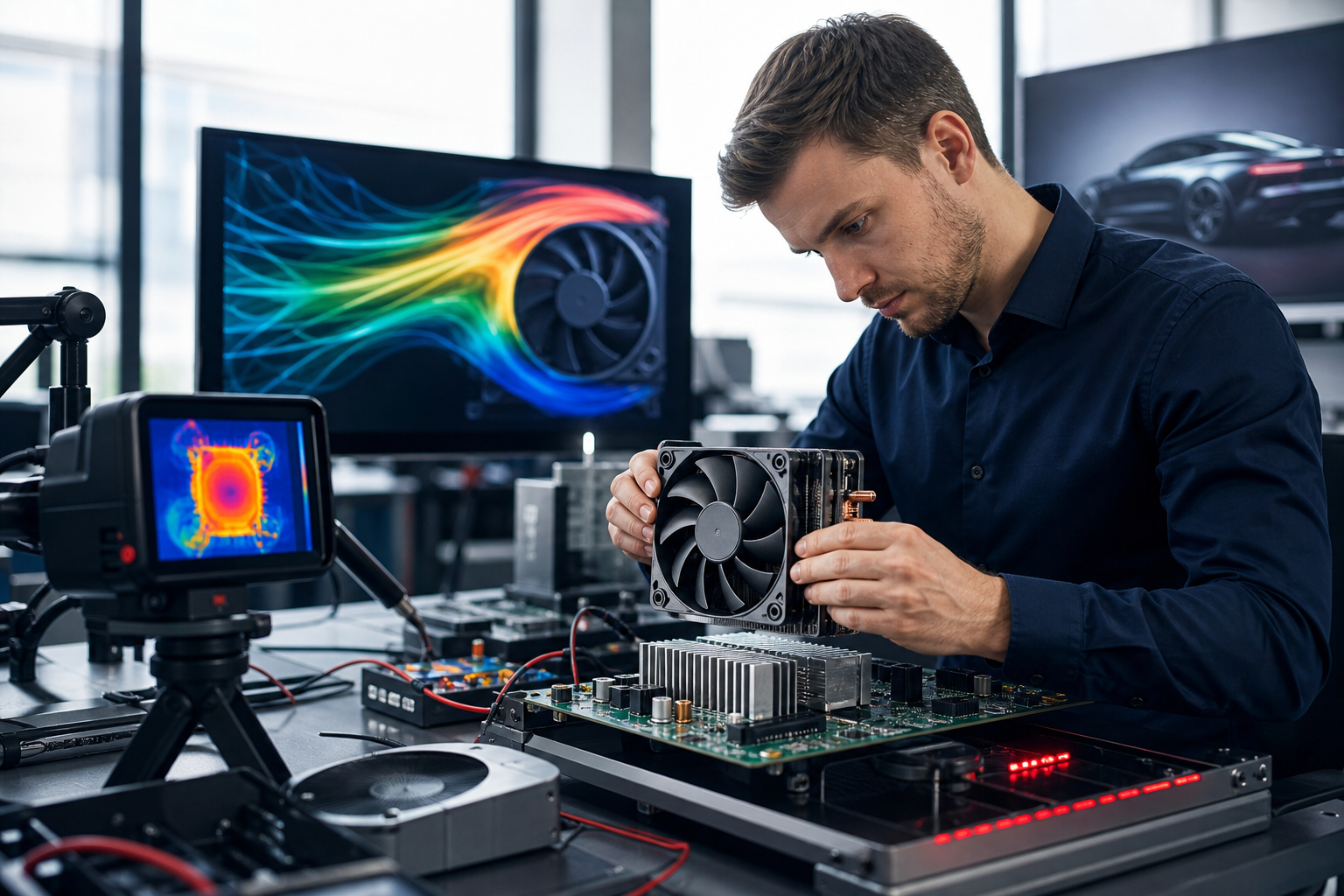
Mechanical engineers usually get into trouble with 3D vapor chambers at the point where the enclosure is already fixed, the hotspot map is already ugly, and the noise target has little room left. The right move is earlier than that. A 3D vapor chamber belongs in the thermal concept stage, when you can still shape the package around heat flux, mounting loads, and the space the product actually has.
That is the core decision. If the design needs localized heat spreading in a tight envelope, a 3D vapor chamber can reduce hotspot temperature, support lower fan speed, and preserve form, fit, and function. If the team treats it like a thicker copper plate with a new label, the result is usually a weak wick decision, poor mechanical support, or a chamber that never gets to full use.
The market data backs up the shift. DataIntelo reports the vapor chamber market at $3.8 billion in 2025, with a forecast of $9.1 billion by 2034 at a 10.2% CAGR, and copper holding over 61.3% of material share. That is not niche activity. It is a design category with real pressure behind it, especially in compact electronics where the thermal load keeps rising.
A 3D vapor chamber works best when the cooling problem is geometric as much as thermal. It spreads heat across a larger effective area without forcing the enclosure to grow, which is why it fits crowded medical devices, telecom hardware, EV charging systems, and compact industrial controls.
YS Tech USA has noted that engineers are moving 3D vapor chambers from niche use into mainstream practice because enclosures are tighter, compute loads are higher, and LED and laser packages are putting more heat into smaller footprints. That matches what I see in real programs. The heat source is no longer the only issue. The available surface, airflow path, and mounting stack all matter at the same time.
The internal YS Tech USA guide on what 3D vapor chambers are and why thermal management relies on them is useful because it frames the chamber as a system-level choice, not a late add-on. The practical lesson is simple. Define the thermal envelope, the board stack, the mechanical stack, and the airflow constraint before the enclosure gets frozen.
A chamber with good thermal potential can still fail in a bad package. In my experience, that failure usually shows up as a late fan increase, a thicker heatsink, or a housing change that costs schedule. Those are expensive fixes because they come after tooling or board layout is already too far along.
Start with geometry, then work backward into the wick and support structure. A conformal 3D vapor chamber is useful when the product does not give you a flat plane, because the chamber can follow the mechanical envelope and place high conductivity where the hotspot actually sits.
The geometry decision should include the heat source location, the allowed stack height, and how the chamber will sit against adjacent parts. Stanford's 2022 thesis on vapor chamber design reports a hybrid microporous evaporator wick that removed more than 150 W from a 5 x 5 mm hotspot, which equals more than 600 W/cm² heat flux, with thermal resistance of 0.02 °C cm²/W. That is a strong reference point, but it only matters if the package lets the wick and cavity do their work under real operating conditions. You can read the thesis details in the Stanford vapor chamber study.
Define the operating envelope before you sign off on the thermal model. That means startup cold conditions, steady-state load, transient pulses, duty cycle, and the worst-case heat flux at the hotspot. Those inputs tell you whether the chamber needs a sintered wick, a thinner cavity, a stronger support pattern, or a different material stack.
The wick is not a minor detail. YS Tech USA's vapor chamber guidance points out that key limits come from wick design and geometry, and the failure mode is capillary limit when liquid return cannot keep up with evaporation. ToneCooling's vapor chamber design guide also notes that wick efficiency depends on porosity, permeability, and structural integrity, and that sintered metal wicks are often used for high power applications because they pump liquid more effectively.
That means you should ask for wick data, not just chamber dimensions. Ask for capillary return limits, startup behavior, and orientation sensitivity. If the product may run in more than one orientation, that request belongs in the specification, not in a later debug meeting.
Mechanical support matters more as chambers get thinner. Stanford's thesis states directly that mechanical design and reliability are crucial to avoid breakdown or leakage from high internal pressure, and it studied an ultra-thin 1 mm-thick, 15 x 15 mm² silicon vapor chamber using cavity area, cavity thickness, fillet radius, circular cavity design, ribs, crossbars, and micro-post arrays.
That work points to the right question for mechanical engineers. How will the chamber hold shape under clamp load, vibration, and thermal cycling? A chamber that performs on the bench but leaks or bows in the field is a packaging failure, not a thermal win.
The internal YS Tech USA article on enhancing device thermal efficiency with 3D vapor chambers is useful for teams that need to connect chamber selection with the rest of the cooling stack. That is where a fan curve, heatsink density, and vapor chamber geometry need to be reviewed together.
Do not treat a 3D vapor chamber as a bigger copper spreader. Copper conducts well, and ToneCooling lists it at 385 W/m·K versus 205 W/m·K for aluminum, but conduction alone does not solve a concentrated hotspot inside a cramped enclosure. The chamber works because phase change moves heat across the surface with much lower temperature rise than a solid plate, and that behavior is only reliable when the wick, cavity, and support system are right.
Do not wait until prototype build to define the heat flux map. If you learn the hotspot size after the housing and board are frozen, you have already limited your options. That is when teams start trading acoustic noise for temperature, and the product ends up louder than anyone planned.
Do not ignore material tradeoffs either. ToneCooling notes that aluminum is lighter for weight-sensitive designs, while copper is preferred for high power applications, and hybrid material constructions can balance thermal transfer and structural needs. In automotive, medical, and portable equipment, that choice can shift both mass and cost in a meaningful way.
Do not assume one setup works across all orientations or duty cycles. A chamber that performs during a 10-minute lab run can behave differently during long dwell times, cold starts, or intermittent pulse loads. If the product sees real field variation, specify it in the thermal requirements and ask the vendor to validate against it.
Surface chemistry can make or break long-term performance. Stanford's thesis found copper surface oxidation to be a critical degradation mechanism, and it recommends pre-oxidizing the copper evaporator wick to form hydrophilic cupric oxide, CuO, along with a reliable superhydrophilic layer and maintenance protocols to preserve functionality over time.
That is the sort of detail that gets missed when teams focus only on peak watts. A chamber can test well on day one and still lose performance if the surface chemistry shifts or the wick dries out unevenly over life. If the product is medical, telecom, or industrial, that long-term behavior deserves the same attention as initial thermal resistance.
The reliability case is also supported by market adoption. DataIntelo's 2026 report says Standard Vapor Chambers held 42.6% share in 2025, Consumer Electronics accounted for 38.4% of revenue share, and Asia Pacific generated $1.6 billion, or 42.1% of global share. Those figures show a mature supply base, which makes it easier to demand stronger validation from suppliers instead of accepting generic specs.
Request test data for thermal resistance, orientation behavior, leak integrity, and cycling stability. Request the chamber's mechanical limits under clamp load and vibration. Request surface preparation details if the wick depends on oxidation or coating control.
That is especially important in custom cooling solutions, where a slight change in geometry can change capillary return or contact pressure. YS Tech USA works across medical, industrial, automotive, energy, lighting, and telecom because the design problem is rarely just airflow. It is usually a mix of thermal spread, packaging, and manufacturing control.
Q: When should a mechanical engineer specify a 3D vapor chamber?
A: Specify it early, when the enclosure is still open to change and the hotspot is already known. The best use case is a compact product with a concentrated heat source and limited room for a larger heatsink or more airflow. That usually comes up in medical devices, telecom racks, EV charging hardware, and industrial controls. If you wait until the package is frozen, you reduce the chamber's value and increase the odds of a re-spin.
Q: What is the biggest technical mistake teams make with vapor chambers?
A: They focus on the plate shape and ignore the wick. The chamber's ability to return liquid to the evaporator sets the real limit, especially under high heat flux or awkward orientation. If the wick cannot keep up, the chamber reaches capillary limit and thermal performance falls off. The fix is to ask for wick data, not just a CAD file and a thermal resistance number.
Q: How do geometry and mechanical support affect performance?
A: Geometry controls how well the chamber reaches the hotspot and how much effective spread area you gain inside the available footprint. Mechanical support matters because thin chambers can deform or leak under pressure, clamp load, or cycling. Stanford's work on ultra-thin chambers shows that ribs, crossbars, micro-posts, and cavity shape all change reliability. A good thermal concept can still fail if the structure cannot hold its shape.
Q: Are copper chambers always better than aluminum ones?
A: No. Copper has higher thermal conductivity, and that is why it is common in high power designs, but it also adds mass. Aluminum is the lighter option and can make sense when weight or cost is tight. Hybrid material designs can balance performance and structure, so the right choice depends on the power density, mounting method, and product target.
Q: What validation data should I ask the supplier for?
A: Ask for thermal resistance across the expected operating range, startup cold behavior, orientation sensitivity, leak integrity, and cycling data. You should also ask for mechanical limits under clamp load and any surface preparation details if the wick depends on oxidation control. If the design is custom, ask for validation against the real duty cycle, not just a nominal steady-state load. That reduces the chance of discovering a field issue after launch.
Q: Do 3D vapor chambers replace fans and heatsinks?
A: No. They work with fans and heatsinks as part of the full cooling architecture. A vapor chamber spreads heat, a heatsink rejects it, and a fan moves air across the fins. If one part is underspecified, the others have to carry too much load and the thermal margin disappears.
YS Tech USA is a premier designer and manufacturer of thermal solutions, specializing in low noise, high-performance DC axial fans, blowers, and heat sink technologies. Located in Huntington Beach, California, we deliver reliable, high-quality products for demanding applications across various industries.
At YS Tech USA, we offer the best of both worlds: the capabilities of a large company with the personalized service of a small one. We collaborate closely with our customers to understand their specific thermal needs and provide customized solutions tailored to their unique requirements.
Our extensive product range includes both modified standard and custom solutions, designed to tackle a wide array of thermal challenges. Whether you need a high-performance fan for a new project or a custom heat sink for an existing application, our team is ready to assist.
With over three decades of industry experience, YS Tech USA has a proven track record of delivering innovative and effective thermal solutions. Contact us today to discover how we can help you address your thermal control challenges.
What does your next enclosure need most, lower noise, smaller size, or a thermal design review before the board layout gets locked?
Charlie Taylor: Charlie is a seasoned industry executive with a demonstrated history of working in the electronics manufacturing industry supporting engineers and buyers with ideas and technical support for fans, blowers and heat sinks.
Are you still treating heat like a waste product you can shove into a bigger fan? If you are, you...
Engineers and designers are now pushing 3D vapor chambers from niche curiosity into mainstream...

Have you ever wondered how manufacturers are adapting to meet the surging demand for...