Key Takeaways
- Start thermal work at the specification stage, not after the enclosure is fixed, because airflow, impedance, acoustics, and IP rating all change the cooling outcome.
- Match fan, blower, and heatsink selection to the real heat load and pressure drop, then validate it with CFD before tooling.
- Treat enclosure temperature as a design limit, not a rough target. A common industrial target is to stay below 85°C inside the enclosure under maximum load, and overheating remains tied to more than 30% of premature device failures, according to AIMPCB's enclosure thermal design guidance.
- Move to liquid or hybrid cooling when rack density climbs beyond air-cooling limits. Industry guidance shows traditional air architectures hold up best near 20 kW per rack, while performance drops fast as density moves toward 40 to 80 kW.
- Use engineering collaboration early. YS Tech USA supports CFD, FEA, custom heatsinks, and EC motor fans so mechanical teams can cut re-spins and reduce schedule risk.
Introduction
Mechanical engineers are being asked to solve cooling problems that used to belong to a late-stage component buyer. Industrial systems now pack more power into smaller spaces, and thermal management has to cover airflow path, enclosure geometry, vibration, noise, reliability, and manufacturability in one pass. YS Tech USA builds around that reality with thermal cooling solutions that include AC, DC, and EC fans, centrifugal blowers, and heat sinks.
The pressure is not abstract. The Engineering Institute of Technology's thermal management guidance for high-load mechanical systems notes that excessive thermal loads can reduce performance, accelerate wear, and cause catastrophic failures. Persistence Market Research projects the U.S. Thermal management technologies market at US$5.8 billion in 2026, which tells you the demand is broad and growing, but the real signal is earlier in the design cycle, where the wrong cooling choice can lock in rework.
If you are responsible for a machine, enclosure, rack, or power subsystem, the question is simple. What do you change first when the temperatures run hot, and what do you do when the first fix does not hold? The guide below gives you a step-by-step path, with the likely failure at each stage and the recovery action that gets the design moving again.
Table of Contents
- Step 1: Define the thermal limit and load profile
- Step 2: Map the airflow path through the real geometry
- Step 3: Size fans and blowers to system impedance
- Step 4: Place heatsinks where conduction and spreading matter most
- Step 5: Validate the design with CFD and test data
- Step 6: Match enclosure cooling to the environment
- Step 7: Decide when air cooling is no longer enough
- Step 8: Lock reliability, service life, and manufacturability into the spec
- Critical recovery actions
- FAQ
- About YS Tech USA
Step 1: Define The Thermal Limit And Load Profile
Set the temperature ceiling before you pick hardware. That gives you a real target for component selection, airflow, and enclosure design.
Start with junction temperature, internal ambient, and the maximum load case that the machine will see in production. Michigan Technological University notes that mechanical engineers work with motion, energy, and force to make designs function safely, efficiently, and reliably, and that includes heating and cooling systems. In industrial cooling, that means the first job is to define the heat load, the ambient envelope, and the allowable rise above ambient before anyone talks about part numbers.
If this step goes wrong: The design starts from a guessed temperature target, so every downstream choice is sized against the wrong number. Rebuild the load profile from actual power dissipation, duty cycle, and ambient conditions, then restart the specification in the same day.
Step 2: Map The Airflow Path Through The Real Geometry
The enclosure geometry should guide the cooling plan, not fight it. Air has to move through the actual obstruction pattern, cable routing, filter stack, and internal component layout.
Trace the inlet, exhaust, and recirculation paths before you select a fan or blower. The EIT article on thermal management in high-load mechanical systems frames heat transfer through conduction, convection, and radiation, which is the right way to think about an enclosure: the air path is only one part of the picture, but it is usually the part that gets ignored first. We use CFD and physical layout review together because a clean airflow path often removes more heat than a larger fan installed in the wrong place.
If this step goes wrong: The cabinet cools the wrong area and leaves hot spots behind shields, boards, or power modules. Rework the internal layout, open the flow path, and retest before changing the fan size. You can usually re-run this step in the next prototype cycle.
Step 3: Size Fans And Blowers To System Impedance
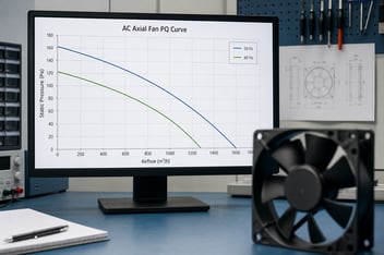
Choose airflow based on pressure drop, not catalog airflow alone. A fan that looks large on paper can fail in a restricted path if the static pressure curve is wrong.
Industrial systems often need high static pressure, especially when filters, heat sinks, long ducting, or dense electronics are in the path. YS Tech USA supports axial fans, EC motor blowers, and high-performance heat sinks, which matters because airflow and pressure need to be matched to the actual system curve, not to a generic CFM target. In industrial designs, we also pay attention to PWM control, bearing type, and acoustic noise in dBA, since a solution that meets temperature but fails on noise or life is still a bad spec.
If this step goes wrong: The fan moves air on the bench but starves under real restriction. Re-spec the fan or blower against the measured impedance curve, then verify the operating point against the duty cycle before procurement releases the part.
Step 4: Place Heatsinks Where Conduction And Spreading Matter Most
Use heatsinks where heat enters a surface that can spread it effectively. That is where conduction and surface area do the most work.
Put the heatsink in the path of the strongest thermal bottleneck, not where it is easiest to mount. A good sink can reduce local thermal resistance, but only if the contact area, mounting pressure, and fin geometry fit the heat source and the airflow. In industrial electronics, the wrong fin density can choke the fan, while the right skived or extruded profile can move the same heat with less noise and lower power draw.
If this step goes wrong: The heatsink looks correct but leaves the source too hot because contact and airflow are mismatched. Recheck interface material, mounting force, and fin spacing, then test again on the same hardware in 24 hours or less.
Step 5: Validate The Design With CFD And Test Data
Use simulation to find the weak points before tools are cut. Then prove the result with measured data.
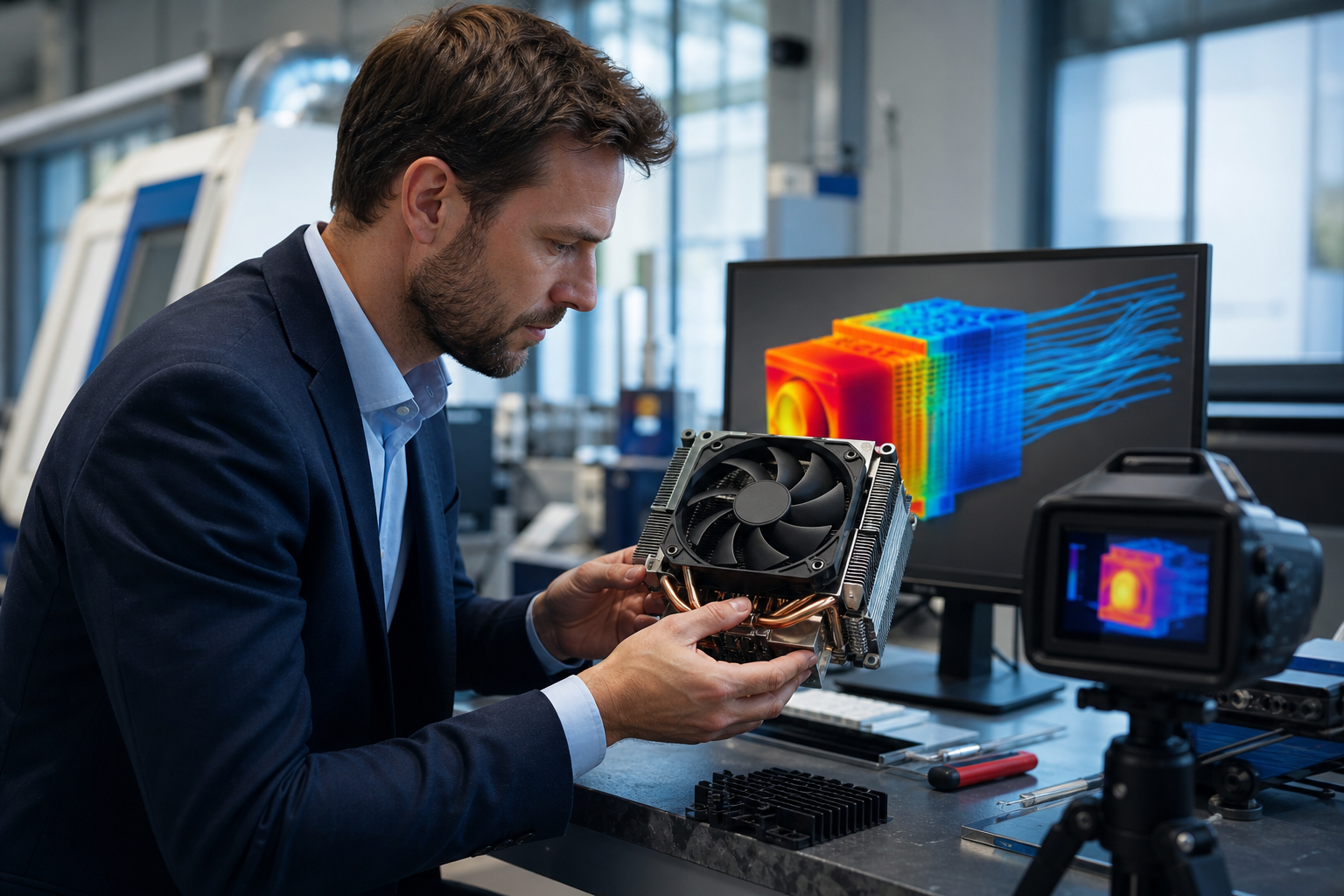
CFD is most useful when it is tied to a real enclosure model, actual fan curve, and known heat input. YS Tech USA includes CFD, FEA, and thermal simulation in its engineering process because this is where many re-spins are avoided. A 2026 market analysis from YS Tech USA also points to EC motor fans and blowers, custom heatsinks, and CFD-validated cooling assemblies as the products OEMs are specifying earlier, not later.
If this step goes wrong: The model predicts safe temperatures, but the prototype runs 10 to 15 degrees hotter. Check boundary conditions, fan curve data, and mesh quality, then rerun the model before changing hardware. The recovery can begin the same day if the test setup is stable.
Step 6: Match Enclosure Cooling To The Environment
Indoor cooling and outdoor cooling are different jobs. Moisture, dust, UV exposure, washdown, and vibration change what will survive in service.
For industrial applications, an IP43 design may be enough in one location, while IP55, IP56, or IP68 is required in another. YS Tech USA's 2026 thermal management trends article reflects a broader market shift toward earlier specification of EC fans, custom heatsinks, and CFD-validated assemblies, and that is especially true when the environment is harsh. The point is simple: the cooling design has to survive the same conditions as the machine.
If this step goes wrong: The thermal solution performs in the lab and fails after exposure to dust, water, or temperature cycling. Move to sealed connectors, rugged materials, and the correct IP-rated design, then repeat environmental testing before release.
Step 7: Decide When Air Cooling Is No Longer Enough
Air cooling has a limit, and rack density makes that limit visible fast. Once the thermal load rises too far, hybrid or liquid cooling becomes the rational choice.
Diabatix reports that traditional air architectures stay efficient up to around 20 kW per rack, but performance and power usage effectiveness begin to deteriorate sharply as densities move toward 40 to 80 kW. The same research notes that AI and accelerated compute racks are already being designed at 50 to 100 kW and beyond in leading deployments. That is why mechanical teams should treat liquid cooling as a specification decision, not a rescue plan after the first prototype overheats.
If this step goes wrong: The team keeps forcing air cooling into a power density it cannot hold. Change the cooling architecture before the next build, then separate process cooling from equipment cooling if the temperature difference demands it.
Step 8: Lock Reliability, Service Life, And Manufacturability Into The Spec
The last step is making sure the cooling solution can be built, serviced, and trusted in volume. Reliability data matters here, because thermal design does not end when the prototype passes.
One industrial fan supplier reports 70,000 hours of service life at 40°C and a mean time between failures of more than 3 years, which is the kind of number buyers want to see when uptime is tied to production or medical use. For mechanical engineers, the point is to look at bearing choice, connector design, stocking support, and test documentation before release. YS Tech USA supports value-added assemblies, label control, stocked programs in California, and design collaboration so the cooling solution fits the manufacturing flow as well as the thermal one.
If this step goes wrong: The design ships with no clear reliability basis, and the field failure becomes a supply problem too. Rebuild the spec around life, compliance data, and production support, then release only after the documentation package is complete.
The Recovery Actions That Save The Most Implementations
The actions below matter most when the first pass does not hold.
- Rebuild the thermal load profile from real operating data when the starting point is wrong, because every later calculation depends on that number and a false load can waste an entire prototype cycle.
- Recheck airflow path and enclosure geometry before changing hardware, since many hot spots come from blocked flow, recirculation, or poor inlet and outlet placement.
- Respec the fan or blower against the measured impedance curve, not the catalog airflow figure, because pressure drop is where many industrial designs fail.
- Correct the interface, mounting force, and fin geometry when a heatsink underperforms, because contact quality often decides whether the solution works or stalls.
- Keep the recovery mindset in every review: fix the specific thermal cause, rerun the test, and move forward with the new data instead of defending the first draft.
Build Cooling So The Next Revision Starts Closer
A good recovery plan does more than save one build. It teaches the team where the real thermal limits sit, which assumptions were weak, and which specifications need to move earlier in the process. That is how mechanical engineering teams shorten the next cycle and reduce the chance of a late-stage thermal surprise.
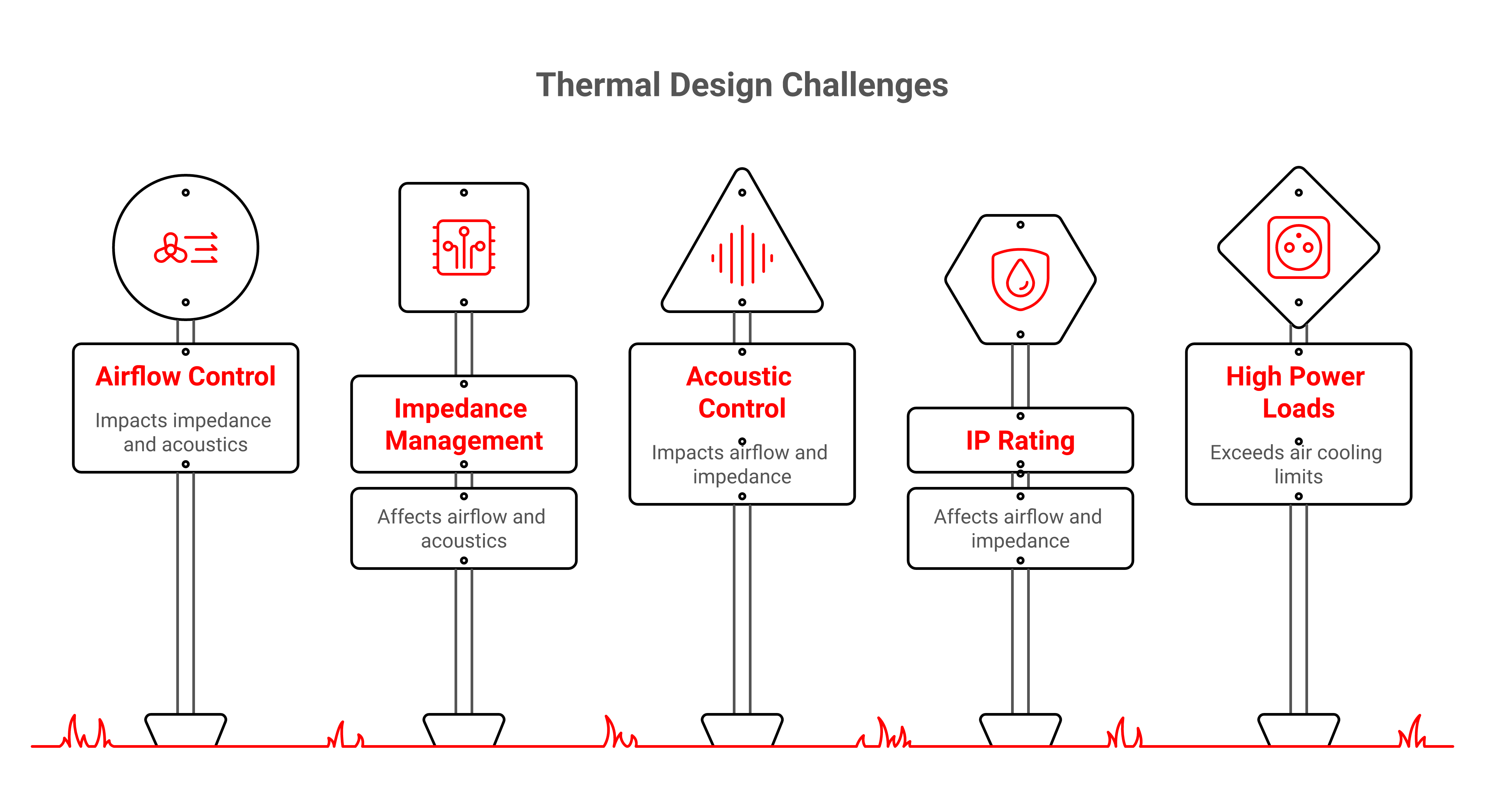
We see the best results when airflow, acoustics, IP rating, CFD, and manufacturability are specified together. That is the point of a complete thermal partner: fans, blowers, EC motors, and heat sinks built to fit the application, not force the application to fit the part. When the thermal design is handled this way, the next prototype starts from a stronger baseline.
FAQ
Q: When should a mechanical engineer start thermal design on an industrial product?
A: Start it before enclosure dimensions and major mechanical features are frozen. Thermal limits affect fan placement, ducting, connector choice, and even service access. If you wait until after tooling, the cooling options shrink fast. The best time is during the first architecture review, when changes are still cheap.
Q: What is the most common mistake in industrial cooling?
A: The most common mistake is selecting airflow by catalog CFM without checking system impedance. A fan can look strong on paper and still underperform once filters, heat sinks, and wiring fill the enclosure. That is why static pressure, not just free-air airflow, has to be part of the spec. CFD and bench testing close the gap between theory and the real build.
Q: When should a design move from air cooling to liquid cooling?
A: Move when air can no longer hold the temperature target without unacceptable noise, size, or power penalties. In high-density rack applications, traditional air cooling stays most viable near 20 kW per rack, while performance drops as densities approach 40 to 80 kW. At that point, direct-to-chip or immersion liquid cooling becomes the more practical path. The decision should be made at the architecture level, not after repeated overheating events.
Q: How do IP ratings affect cooling performance?
A: IP ratings limit how air can move, how much dust gets inside, and what sealing parts must survive. Higher protection often means tighter paths, more pressure drop, and more attention to connector design and material choice. That tradeoff needs to be part of the thermal model. A sealed design can still cool well if the pressure curve and flow path are planned correctly.
Q: Why do heatsinks fail when the fan is already strong enough?
A: A heatsink can fail when contact resistance is high or the fin geometry does not match the available airflow. If the base is not seated well, heat never gets into the sink efficiently. If the fins are too dense, airflow stalls and pressure rise increases noise without improving cooling. The fix is usually in interface quality, fin spacing, or both.
Q: What support helps reduce re-spins in thermal design?
A: Engineering support that combines CFD, FEA, custom product development, and manufacturing input cuts risk early. That kind of support helps teams catch airflow dead zones, bad pressure matches, and assembly issues before the first build. It also makes it easier to move from concept to production without changing the cooling concept late. For NPI teams, that saves time and reduces schedule slip.
About YS Tech USA
YS Tech USA is a premier designer and manufacturer of thermal solutions, specializing in low noise, high-performance DC axial fans, blowers, and heat sink technologies. Located in Huntington Beach, California, we deliver reliable, high-quality products for demanding applications across various industries.
At YS Tech USA, we offer the best of both worlds: the capabilities of a large company with the personalized service of a small one. We collaborate closely with our customers to understand their specific thermal needs and provide customized solutions tailored to their unique requirements.
Our extensive product range includes both modified standard and custom solutions, designed to tackle a wide array of thermal challenges. Whether you need a high-performance fan for a new project or a custom heat sink for an existing application, our team is ready to assist.
With over three decades of industry experience, YS Tech USA has a proven track record of delivering innovative and effective thermal solutions. Contact us today to discover how we can help you address your thermal control challenges.
Author
Charlie Taylor: Charlie is a seasoned industry executive with a demonstrated history of working in the electronics manufacturing industry supporting engineers and buyers with ideas and technical support for fans, blowers and heat sinks.
Read On