
- YS TECH USA Inc blog
- Thermal Management,
- Fan Selection,
- Electronics Cooling,
- Static Pressure,
- AC Axial Fan Sizing,
- Airflow Requirements,
- Cooling System Design
- Airflow and Static Pressure for AC Axial Fans
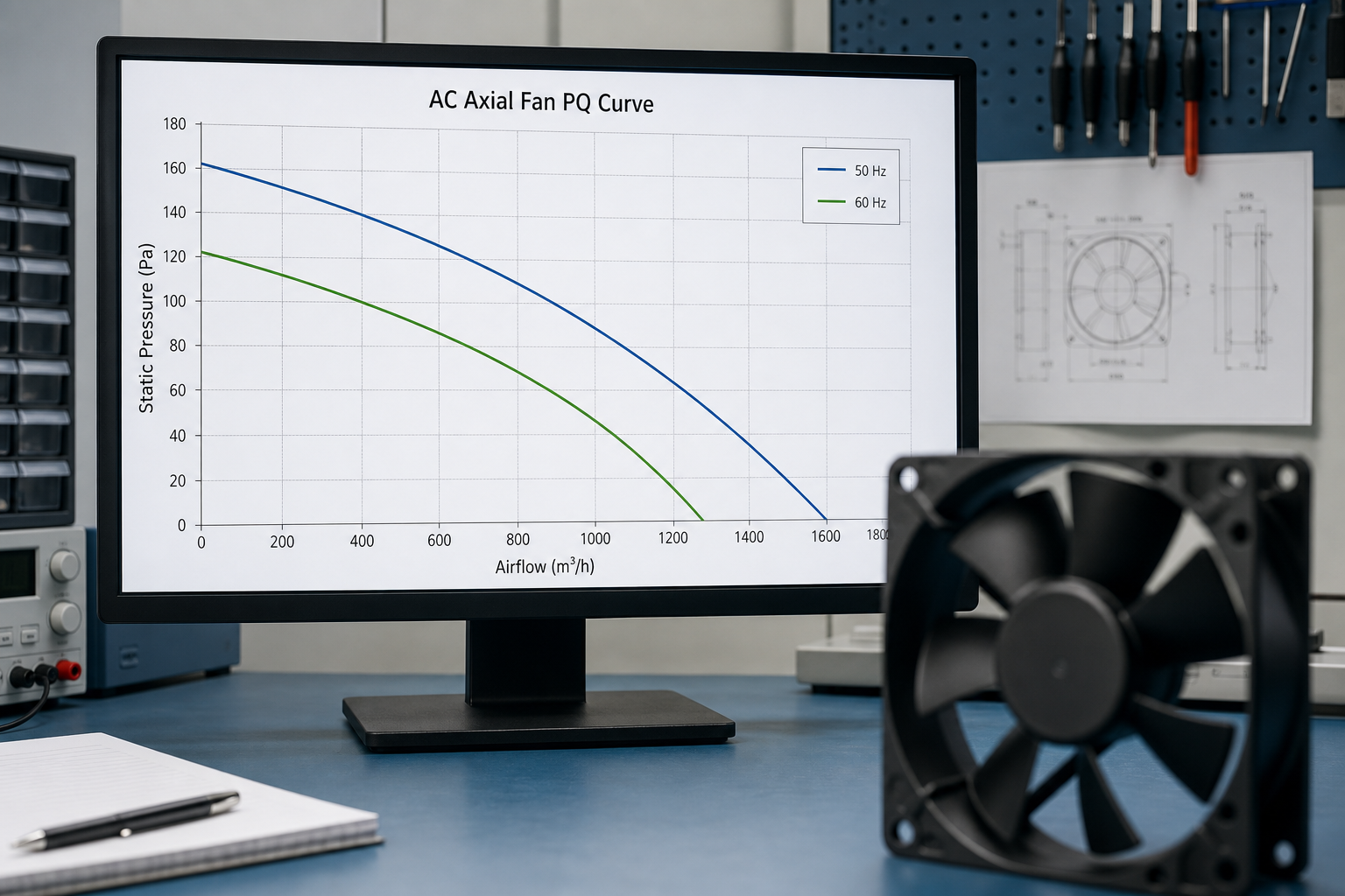
Most fan sizing mistakes don't come from picking a bad fan. They come from sizing a fan using only its highest CFM number, which is measured in open air with nothing blocking it, and then installing that fan behind a filter, a PCB, or a tightly packed enclosure where it never gets close to that number. Getting AC axial fan sizing right means working from two numbers together, required airflow and static pressure, not one number in isolation.
This is the calculation engineers actually need, along with the reasoning behind it.
Step one: calculate the airflow you need
Start with how much heat the enclosure has to reject and how much temperature rise is acceptable above ambient. The standard formula, used across the industry for forced-convection electronics cooling, is:
Required CFM = (3.16 x Total Heat in Watts) / Allowable Temperature Rise in °F
Or in metric: Required CFM = (1.76 x Total Heat in Watts) / Allowable Temperature Rise in °C
Worked example: an enclosure dissipates 150W and the components inside can tolerate a 15°C (27°F) rise above ambient before hitting their thermal limits.
Metric: (1.76 x 150) / 15 = 17.6 CFM
Imperial: (3.16 x 150) / 27 = 17.6 CFM
Both versions of the formula agree, which is a useful sanity check when you're working from a datasheet that mixes units. That 17.6 CFM number is your baseline. It is not the number you should put on a purchase order, for reasons that come next.
Step two: understand why static pressure changes everything
Airflow and static pressure have an inverse relationship for any given fan. As backpressure increases, air pushed through drops, and a fan cannot deliver its maximum rated CFM and its maximum static pressure at the same time. This relationship is plotted on a PQ curve (pressure-quantity curve), which every reputable fan datasheet includes.
Your enclosure has its own resistance to airflow, called system impedance, created by filters, grilles, internal components, and cable routing. That resistance also has a curve, and it follows roughly a square-law relationship: static pressure increases with the square of airflow through a given restriction. The point where your enclosure's impedance curve crosses the fan's PQ curve is the fan's actual operating point, the real airflow and pressure it will deliver once installed. That operating point is almost always lower than the fan's rated open-air CFM.
This is why two fans with the same CFM rating can perform very differently in the same enclosure. A fan built for higher static pressure will hold more of its airflow as backpressure rises, while a fan optimized purely for open-air CFM can fall off sharply once it's behind a filter.
For more on how these two specs trade off against each other, see YS Tech's breakdown of static pressure vs. airflow.
Step three: build in a margin, because your impedance estimate is a guess
Few engineers can precisely calculate system impedance before a design is built and tested, which means the 17.6 CFM baseline from step one has to be oversized to survive real-world conditions like filter loading, dust accumulation, and component changes over the product's life.
A commonly used safety margin is 25 to 50 percent above the calculated baseline to account for a clean system with a filter. When system impedance is genuinely unknown or the enclosure is heavily restricted, doubling the calculated CFM is the more conservative, and more common, rule of thumb. Applied to the 17.6 CFM example:
| Scenario | Multiplier | Target Fan Rating (CFM) |
|---|---|---|
| Clean system, light restriction | 1.25x | 22 CFM |
| Filtered enclosure, normal use | 1.5x | 26.4 CFM |
| Unknown impedance, heavily restricted | 2x | 35.2 CFM |
Step four: size against the PQ curve, not just the CFM number
Once you have a target CFM with margin applied, the real sizing step is checking that number against the fan's PQ curve at your enclosure's expected static pressure, not against its open-air rating. A fan rated for 40 CFM at 0 inches of water gauge might only deliver 22 CFM at the static pressure your filtered enclosure actually creates. If you don't have a measured impedance curve for your enclosure, request one from your fan supplier's application engineering team, or test a candidate fan directly in the enclosure before finalizing a design.
For most standard electronics enclosures, this is where a mid-range AC axial fan does the job well. For higher-heat, less accessible equipment, the sizing math tends to land on the higher-CFM, higher-static-pressure end of a manufacturer's line. See Best AC Axial Fans for High-Heat Equipment for how six specific models stack up once static pressure, IP rating, and bearing type are factored in alongside CFM.
When a catalog fan's PQ curve doesn't clear your system impedance with enough margin, that's a sign to look at a higher-pressure model or a custom configuration rather than oversizing blindly. See YS Tech's 2026 custom thermal design trends for how blade profile and speed get adjusted to hit a specific operating point.
All of the fans referenced above are part of YS Tech USA's industrial AC fan line.
Frequently asked questions
How do you calculate the CFM needed for an electronics enclosure?
Use Required CFM = (3.16 x Total Heat in Watts) / Allowable Temperature Rise in °F, or the metric equivalent, (1.76 x Total Heat in Watts) / Allowable Temperature Rise in °C. This gives a baseline airflow figure, which then needs a safety margin applied for real-world system impedance before it becomes a fan spec.
What's the difference between airflow and static pressure in a fan spec?
Airflow (CFM) measures how much air a fan moves with nothing blocking it. Static pressure measures how much resistance the fan can push air against. The two have an inverse relationship, plotted on a fan's PQ curve, and a fan's actual performance in an enclosure is the point where that curve crosses the enclosure's own resistance curve, not the fan's peak rated CFM.
How much safety margin should you add to a calculated CFM?
A 25 to 50 percent margin above the calculated baseline is standard for a clean, filtered system. When system impedance is unknown or the enclosure is heavily restricted, doubling the calculated CFM is a more conservative and commonly used rule of thumb.
What is a fan's PQ curve and why does it matter for sizing?
A PQ curve (pressure-quantity curve) plots a fan's airflow against static pressure across its full operating range. It matters because a fan's real-world airflow is set by where that curve intersects your enclosure's system impedance curve, which is almost always lower than the fan's maximum open-air CFM rating.
Do higher-CFM fans always cool better?
No. A high-CFM fan optimized for open-air performance can lose airflow quickly under backpressure, while a fan with a flatter PQ curve at higher static pressure can outperform it once installed behind a filter or in a restricted enclosure. Matching the fan to your actual system impedance matters more than the headline CFM number.
Read On

Why AC Axial Fan Selection Is Hard for Machinery Cooling
Ask an engineer why AC axial fan selection is hard and most will point to one number, usually CFM...

Best AC Axial Fan Suppliers Compared for OEMs
Ask ten OEM procurement teams which AC axial fan supplier is "best" and most will answer with a...

Best AC Axial Fans for High-Heat Equipment
Not every AC axial fan built for a hot enclosure is actually built for a hot enclosure. Plenty of...