Key Takeaways
- 3D vapor chambers are now used for heat loads in the 200 W to 1000 W range, especially in servers, telecom racks, EV electronics, and compact industrial systems.
- Their value is spread heat, not finished cooling. The final result still depends on fin density, airflow path, blower static pressure, and the enclosure around the part.
- Cost sits in the middle. Nextron Group says a 3D vapor chamber costs about twice as much as a heat pipe or plate, yet still costs far less than liquid cooling in many designs.
- For high-performance devices, the real design choice is system level. A vapor chamber changes how heat enters the heatsink. It does not remove the need for engineered air-side cooling.
- Teams that spec fans, blowers, and heatsinks early can avoid re-spins that come from treating thermal spreading as a late fix.
Introduction
3D vapor chambers change thermal management because they move heat in two directions at once, across the base and upward into the fins. That matters when a device has high power density, a tight enclosure, and only a small window between acceptable junction temperature and field failure.
The category is moving fast. Nextron Group says a 3D vapor chamber can handle over 500 watts of power, while T-Global Technology says 3D vapor cooling can handle over 250 W in compact spaces. MyHeatSinks puts typical vapor chamber heat sinks in the 200 W to 600 W range, and says newer designs with improved wick structures can go beyond 1000 W. Those are not small gains. They show where the design pressure is headed.
For thermal engineers and mechanical engineers, the harder question is not whether 3D vapor chambers spread heat well. It is how the rest of the stack reacts once that heat is delivered more evenly to the fins. That is where fan curve selection, static pressure, acoustic targets, fin geometry, and system airflow path decide whether the design passes in the lab and survives in the field.
Table of Contents
- Why 3D Vapor Chambers Changed the Heat Spreading Conversation
- Where the Performance Numbers Fit
- Cost, Packaging, and Design Tradeoffs
- How They Interact With Fans and Heatsinks
- Applications in Telecom, EV, Industrial, Medical, and Lighting
- What Engineers Should Specify Early
Why 3D Vapor Chambers Changed the Heat Spreading Conversation
3D vapor chambers matter because they address vertical and horizontal spreading in one part. That makes them useful when a hot component sits far from the fin stack or when a flat base alone cannot move heat fast enough into the full heatsink area.
ToneCooling says to use a 3D vapor chamber when higher power must also be carried up into the fins, which is the exact failure mode many compact designs run into. A heat source may have acceptable device-level thermal resistance on paper, then fail because one small contact zone is trying to feed an oversized load through too little copper.
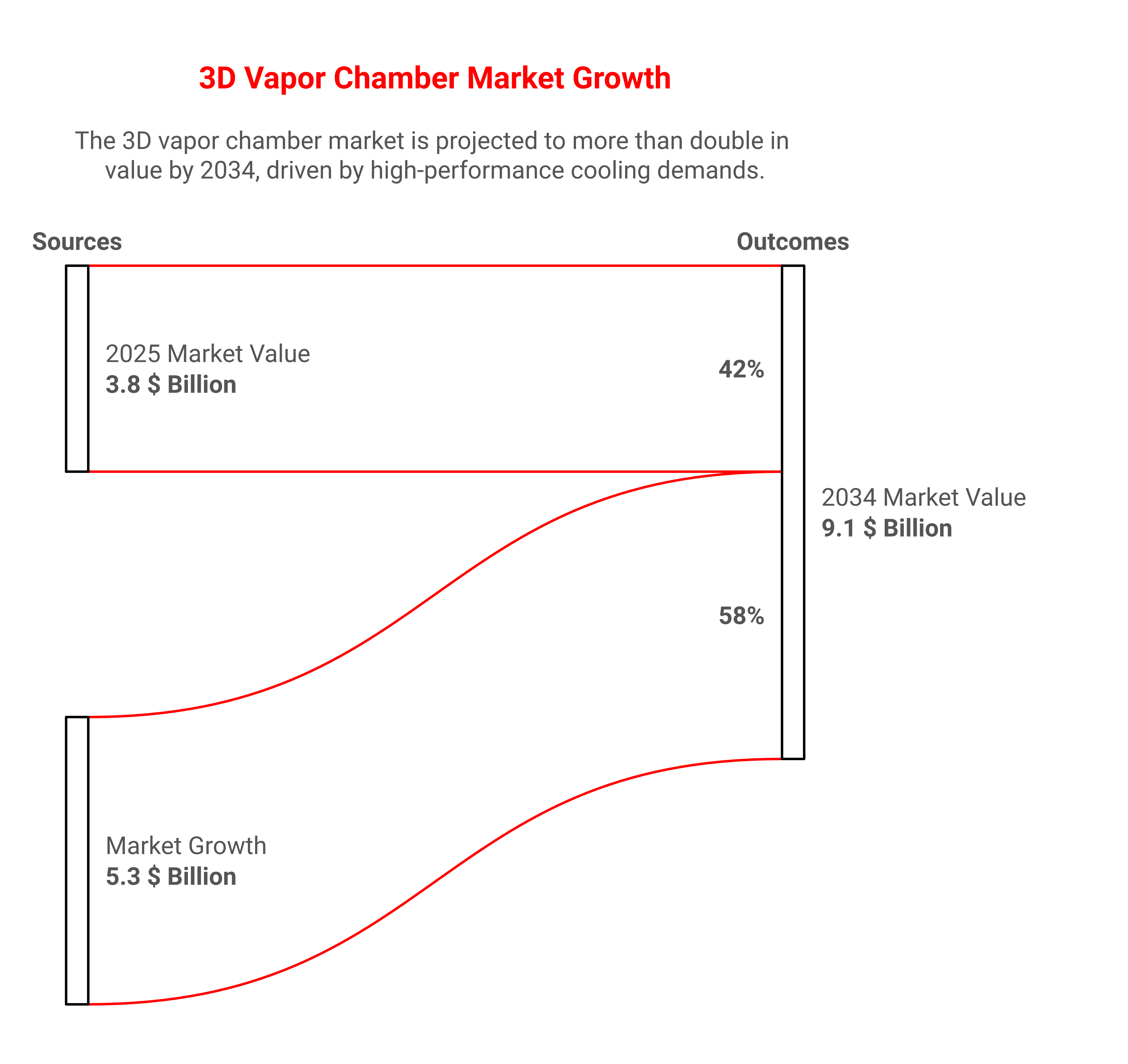
The stronger use case is not cosmetic. It is density. DataIntelo values the global vapor chamber market at $3.8 billion in 2025 and projects $9.1 billion by 2034, with a 10.2% CAGR from 2026 to 2034, which shows how quickly these parts are moving out of niche use and into mainstream hardware programs. The same report points to consumer electronics, data centers, automotive, aerospace, and healthcare as active application areas. DataIntelo's vapor chamber market outlook captures that spread clearly.
Where The Performance Numbers Fit
The headline numbers are useful only if you read them as design targets, not universal truths. A 3D vapor chamber is not a magical material with one fixed conductivity number. It is a two-phase heat spreader whose performance depends on internal wick structure, fill ratio, orientation, footprint, and contact quality.
T-Global Technology says its 3D vapor cooling technology has thermal conductivity above 4400 W/(m·K), which is a vendor claim rather than a material constant, but it shows how aggressively the category is being positioned. The same source says its 3D vapor cooling can handle over 250 W in compact spaces. T-Global's 3D vapor cooling overview is useful because it gives a vendor-side view of where the technology is being aimed.
Nextron Group draws an even clearer boundary. It says air cooling is typically enough up to 350 W TDP, liquid cooling is recommended from 350 W to 1000 W, and immersion liquid cooling becomes necessary beyond 1000 W. It also says recent corporate reports suggest air cooling can effectively handle up to 1000 W, while the optimal threshold for air cooling efficiency is around 500 W. Nextron Group's 3D vapor chamber article places 3D vapor chambers in that middle ground, where the load is too high for basic spreading and too expensive to justify full liquid cooling.
Reference Range For Engineers
| Metric | Practical reading | Engineering implication |
|---|---|---|
| Over 250 w | Compact-space vapor cooling claim from T-Global | Base spreading alone is often not enough |
| 200 w to 600 w | Typical vapor chamber heat sink range from MyHeatSinks | Fan curve and fin density still decide the final junction temperature |
| Over 500 w | Nextron target for 3D vapor chamber use | Serious airflow planning is required, not just a better cold plate |
| Over 1000 w | Upper-end vapor chamber claim from MyHeatSinks | System architecture starts to resemble liquid-class thermal planning |
Cost, Packaging, And Design Tradeoffs
3D vapor chambers are expensive enough to matter, but not so expensive that they sit in a separate category from most air-cooled products. Nextron says the cost is approximately twice as high as traditional heat pipes or plates, while liquid cooling can cost several times more than a 3D vapor chamber. That price gap explains why many teams now look at vapor chambers as a serious middle path.
This is where procurement and engineering intersect. A cheaper part that misses thermal targets is not cheap once it triggers a board re-spin, a heatsink redesign, or a schedule slip. In my experience, the most expensive thermal part is often the one that forces three downstream changes because it was chosen without enough system context.
Packaging pressure is the other constraint. Compact telecom cards, AI accelerator modules, EV power electronics, and medical imaging hardware leave very little room for oversized fin stacks. A vapor chamber can spread heat well, but it also adds thickness, mass, and manufacturing complexity, so the value comes from what it lets the rest of the stack do more cleanly.
How They Interact With Fans And Heatsinks
A 3D vapor chamber does not replace air cooling. It changes the load map that the fan and heatsink must manage. That distinction is important because a spreader can reduce local hotspot temperature while increasing the amount of fin area that now needs to reject heat.
For YS Tech USA, that system view is the point. AC, DC, and EC fans, centrifugal blowers, and high-performance heatsinks are most effective when the vapor chamber and fin stack are designed together, not bought separately and hoped into compatibility. A high static pressure blower can recover performance in a dense fin pack, while a quieter axial fan may be enough if the chamber has already flattened the heat profile and reduced fin-to-fin imbalance.
PatSnap's micro vapor chamber landscape says the innovation window in its dataset spans 2013 to 2026 and identifies four distinct wick or structural architectures. It also notes that Huawei's January 2026 EP patent signals productization, while MIT and CEA-LETI have mapped the thermal design envelope for AI chips facing kW/cm² power densities. PatSnap's micro vapor chamber landscape shows that this is no longer just an academic topic. It is a product engineering race.
What To Specify Early
Start with the heat source location, then define the allowable temperature difference at the component and sink base. After that, lock down the enclosure airflow path, available fan pressure, and the acoustic ceiling. Those choices tell you whether a vapor chamber is the right spreader or just an expensive way to move the bottleneck somewhere else.
You should also specify assembly tolerance and contact pressure early. Vapor chambers are unforgiving of poor interface control, and uneven mounting pressure can erase a good thermal design on the bench. If the base contact is weak, the part carries the story on paper and fails to carry it in the product.
Applications In Telecom, EV, Industrial, Medical, And Lighting
The strongest applications are the ones with high heat density and thin packaging margins. Telecom racks, server boards, EV charging electronics, battery power conversion, industrial motor controls, medical imaging, and entertainment lighting all create the same problem in different forms: too much heat in too little space.
Jamcor says manufacturers across computing, automotive, telecommunications, and mobile tech sectors are turning to 3D vapor chamber cooling systems. That broad adoption tracks with what design teams already see. Once a platform moves into higher power density and tighter acoustics, the thermal stack becomes a cross-disciplinary decision, not a component choice made in isolation.
For medical and industrial programs, the system-level requirement is often reliability under constrained airflow and longer service life. For lighting and telecom, the challenge is high temperature operation with tight noise limits and compact packaging. In those cases, a vapor chamber can make the heatsink more usable, but the fan and enclosure still set the ceiling.
What Engineers Should Do Next
The right next step is to treat 3D vapor chambers as a heat spreading tool inside a full thermal system review. If your design is sitting in the 200 W to 1000 W class, this is the point where spread, sink, and airflow need to be specified together.
We work with thermal engineers, NPI engineers, and mechanical engineers who need more than a parts catalog. They need a thermal stack that matches the power map, the acoustics target, and the enclosure geometry without burning schedule on late-stage rework. If you are designing for telecom, EV charging, industrial controls, medical electronics, or lighting, what would change if your heatsink and airflow path were designed around the vapor chamber instead of after it?
FAQ
Q: What does a 3D vapor chamber actually do in a thermal stack?
A: It spreads heat both across the base and upward into the fins, which lowers hotspot intensity and makes the heatsink area work more evenly. That is especially useful when the heat source is small but the power level is high. In practice, it helps the sink use its full surface instead of leaving part of it underfed. The part still needs proper airflow and contact pressure to deliver useful system performance.
Q: Is a 3D vapor chamber better than a heat pipe?
A: It depends on the geometry and the heat map. Heat pipes move heat well, but a 3D vapor chamber can spread heat across a broader area and support vertical transfer into the fin stack. Nextron says the cost is about twice that of traditional heat pipes or plates, so the choice is usually about performance per packaging constraint, not just raw thermal resistance. For compact high-power products, the extra spread can justify the cost.
Q: When should a team consider liquid cooling instead?
A: When the thermal load, packaging, or noise limit exceeds what a spreader plus air cooling can manage. Nextron places liquid cooling in the 350 W to 1000 W range and immersion cooling beyond 1000 W, although real boundaries shift by design. If your airflow path is restricted and your fin area is already dense, liquid cooling may become the cleaner architecture. The decision should be based on total system loss, serviceability, and cost, not just chip TDP.
Q: What data should a thermal engineer lock down before choosing a vapor chamber?
A: Start with heat load, source size, allowable junction temperature, and enclosure airflow. Then define fan pressure capability, acoustic ceiling, mounting pressure, and available thickness. Those inputs tell you whether the chamber will actually improve the product or simply move the constraint elsewhere. Without those numbers, the design choice is guesswork.
Q: Why is this technology showing up in telecom and EV electronics now?
A: Power density is rising while enclosure space keeps shrinking. DataIntelo says the vapor chamber market is moving from niche use into data centers, automotive, aerospace, healthcare, and other sectors, and the market value is projected to grow from $3.8 billion in 2025 to $9.1 billion by 2034. That growth reflects a real engineering need. More programs now need high heat spreading in a compact envelope with tight reliability limits.
About YS Tech USA
YS Tech USA is a premier designer and manufacturer of thermal solutions, specializing in low noise, high-performance DC axial fans, blowers, and heat sink technologies. Located in Huntington Beach, California, we deliver reliable, high-quality products for demanding applications across various industries.
At YS Tech USA, we offer the best of both worlds: the capabilities of a large company with the personalized service of a small one. We collaborate closely with our customers to understand their specific thermal needs and provide customized solutions tailored to their unique requirements.
Our extensive product range includes both modified standard and custom solutions, designed to tackle a wide array of thermal challenges. Whether you need a high-performance fan for a new project or a custom heat sink for an existing application, our team is ready to assist.
With over three decades of industry experience, YS Tech USA has a proven track record of delivering innovative and effective thermal solutions. Contact us today to discover how we can help you address your thermal control challenges.
Author
Charlie Taylor: Charlie is a seasoned industry executive with a demonstrated history of working in the electronics manufacturing industry supporting engineers and buyers with ideas and technical support for fans, blowers and heat sinks.
Read On